Non-blind area ultrasonic distance measurement probe and distance measurement method

An ultrasonic, non-blind zone technology, applied in radio wave measurement systems, sound wave re-radiation, measurement devices, etc., to achieve the effect of simple structure, easy implementation, and elimination of the influence of crosstalk through waves

Pending Publication Date: 2017-03-08
杭州立方控股股份有限公司
View PDF8 Cites 6 Cited by
  • Summary
  • Abstract
  • Description
  • Claims
  • Application Information

AI Technical Summary

Problems solved by technology

In order to further reduce the measurement blind zon...

Method used


Image

  • Non-blind area ultrasonic distance measurement probe and distance measurement method
  • Non-blind area ultrasonic distance measurement probe and distance measurement method
  • Non-blind area ultrasonic distance measurement probe and distance measurement method

Examples


Embodiment Construction

[0019] The purpose and effects of the present invention will become more apparent by describing the present invention in detail below with reference to the accompanying drawings.

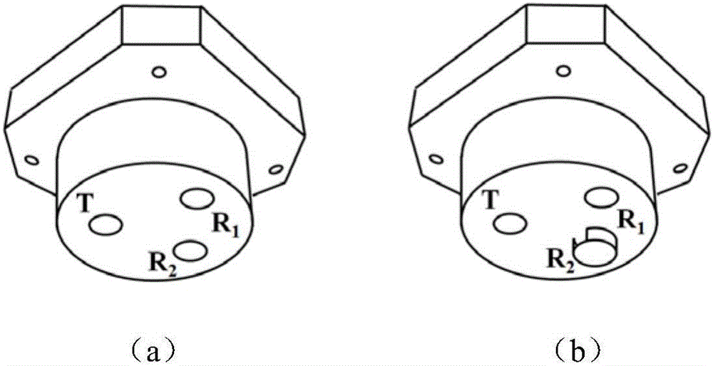
[0020] The present invention provides a non-blind-zone ultrasonic ranging probe based on the principle of anti-phase superposition, which includes an ultrasonic transmitter T and two ultrasonic receivers R 1 , R 2 , two ultrasonic receivers R 1 , R 2 The same distance as the ultrasonic transmitter T and on the same side of the ultrasonic transmitter, the ultrasonic transmitter T and the ultrasonic receiver R 1 , R 2 on the same plane as figure 1 Shown in (a); the second ultrasonic receiver R 2 with the first ultrasonic receiver R 1 The difference is that R 2 Covered by a container with side slots facing the ultrasonic transmitter T, such as figure 1 (b) shown.

[0021] for figure 1 The structural layout shown in (b), the ultrasonic receiver R 1 , R 2 , can be affected by the crosstalk th...


PUM


Abstract

The present invention discloses a non-blind area ultrasonic distance measurement probe and distance measurement method. The probe includes an ultrasonic transmitter T, a first ultrasonic receiver R1 and a second ultrasonic receiver R2 which are located on the same plane; a distance from the first ultrasonic receiver R1 to the ultrasonic transmitter T is equal to a distance from the second ultrasonic receiver R2 to the ultrasonic transmitter T; the first ultrasonic receiver R1 and the second ultrasonic receiver R2 are located at the same side of the ultrasonic transmitter T; the second ultrasonic receiver R2 is covered with a container with a groove formed at the side surface of the container, so that echoes can be isolated; the direction of the groove of the container direclty faces the ultrasonic transmitter T; and the first ultrasonic receiver R1 and the second ultrasonic receiver R2 can be simultaneously subjected to the influence of crosstalk lateral waves of the ultrasonic transmitter T in an equal-amplitude manner. The influence of the crosstalk lateral waves is eliminated through an anti-phase superposition method, and therefore, non-blind area ultrasonic distance measurement can be realized. The non-blind area ultrasonic distance measurement probe and distance measurement method have the advantages of simple structure, easiness in implementation and excellent effects.

Description

technical field [0001] The invention belongs to the field of ultrasonic distance measurement, in particular to an ultrasonic distance measurement probe without a blind zone and a distance measurement method. Background technique [0002] Ultrasound follows the general law of mechanical wave propagation in elastic media. It is characterized by propagating in a straight line, with good beam forming and good directionality. Reflection and refraction will occur at the interface of the medium. After entering the medium, its vibration amplitude Attenuation occurs due to absorption in the medium. Ultrasonic frequencies can be very high, reaching megahertz levels. [0003] The propagation speed of ultrasonic waves in the same medium is basically constant, so by measuring the time it takes for ultrasonic waves to pass a certain distance in the medium, non-contact distance measurement can be realized. In order to improve the accuracy of ranging, it is necessary to accurately measure...

Claims


Application Information

Patent Timeline
IPC IPC(8): G01S15/08G01S7/521
CPCG01S7/521G01S15/08
Inventor 覃勇卢旭鹏朱金刚
Owner 杭州立方控股股份有限公司
Why Eureka
Try Eureka