


Quick Research
Generate reliable direction feasibility study reports for your R&D in just a few steps.

Technical Q&A
Discover and master advanced knowledge NOW. Basics, ideas, possibilities, all at once.

Find Solutions
As an expert in R&D theories, this can generate solutions to your technical problems instantly.

Evaluate Feasibility
Analyze your overall solution with one click, know your potential R&D risks in advance.

Monitor Landscape
Get weekly tech updates, stay abreast of the latest tech innovations and key insights.
Flow rate online monitoring system of transformer oil
A monitoring system and transformer oil technology, applied in the direction of fluid velocity measurement, velocity/acceleration/shock measurement, instruments, etc., can solve the problems of low accuracy of transformer insulating oil flow velocity, transformer blockage, inconvenience, etc., and achieve a safe and reliable measurement method Convenience, low loss, wide frequency effect
- Summary
- Abstract
- Description
- Claims
- Application Information
AI Technical Summary
Problems solved by technology
Method used
Image

Examples
Embodiment 1
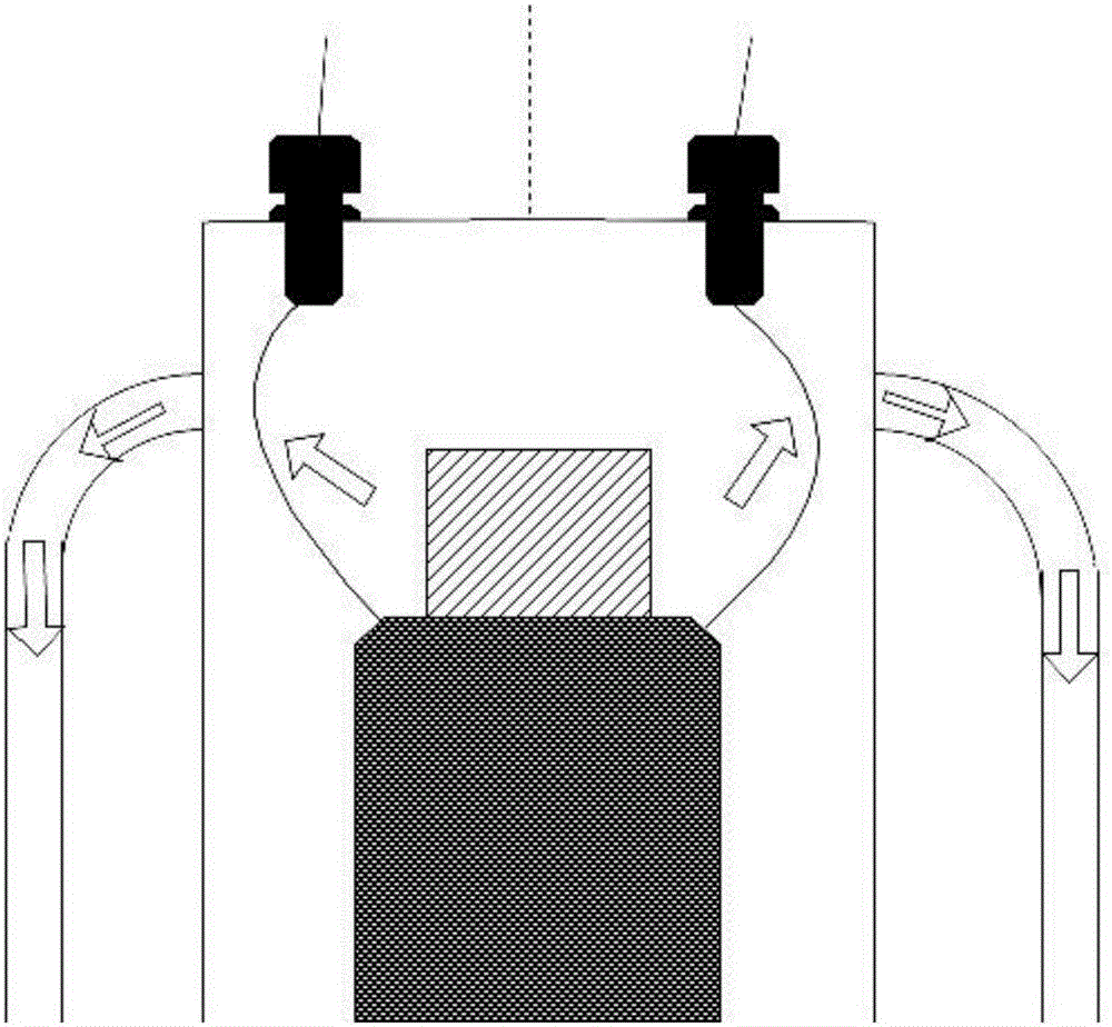
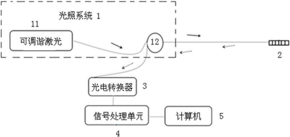
[0025] Such as Figure 2~4 As shown, the transformer oil flow rate online monitoring system of this embodiment includes an illumination system 1, an optical fiber sensor 2, a photoelectric converter 3, a signal processing unit 4, and a computer 5, and an optical fiber sensor is arranged on the six upper convection ports of the three-phase transformer. 2. The illumination system 1 is used to illuminate the optical fiber sensor 2 .
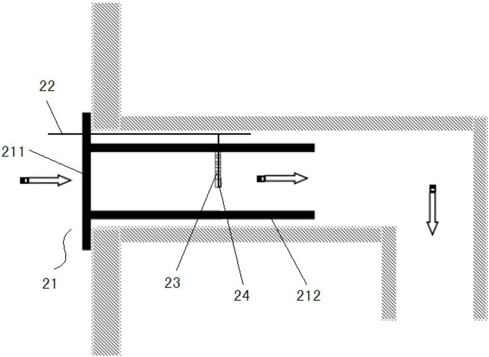
[0026] Each optical fiber sensor of the present embodiment all comprises bracket 21, optical fiber 22, elastic steel sheet 23 and fiber grating 24, and bracket 21 is used for fixing with the entrance of upper convection port, comprises an annular support plate 211, the inner side of annular support plate 211 A cylindrical plug-in 212 is extended, and the outer diameter of the cylindrical plug-in 212 matches the diameter of the upper convection port to ensure that the optical fiber sensor 2 can just be inserted into the upper convection port. The inn...
Embodiment 2
[0057] Such as Figure 7 , Figure 8 As shown, the transformer oil flow rate online monitoring system of this embodiment has the same structure as that of Embodiment 1 in that it includes an illumination system 1, an optical fiber sensor 2, a photoelectric converter 3, a signal processing unit 4 and a computer 5, and this embodiment The structure of the optical fiber sensor 2 is basically the same as that of the embodiment 1, except that the light outlets of the six fiber gratings 24 of this embodiment are sequentially connected in series through an optical fiber 22. In addition, this embodiment also includes an M-Z interferometer 6 and a wave splitter 7 (wavelength division multiplexing), and the M-Z interferometer 6 is used to convert the deviation of the central wavelength of each fiber grating into a corresponding light intensity signal, and pass The wave splitter 7 splits the light, and the wave splitter 7 sends the light of six different central wavelengths to the corre...
PUM
 Abstract
Description
Claims
Application Information
 - R&D Engineer
- R&D Manager
- IP Professional
- Industry Leading Data Capabilities
- Powerful AI technology
- Patent DNA Extraction
Browse by: Latest US Patents, China's latest patents, Technical Efficacy Thesaurus, Application Domain, Technology Topic, Popular Technical Reports.
© 2024 PatSnap. All rights reserved.Legal|Privacy policy|Modern Slavery Act Transparency Statement|Sitemap|About US| Contact US: help@patsnap.com