
Intra-shaft operation rotor wing device

A rotor and main rotor shaft technology, applied in the field of in-axis control of the rotor device, can solve the problems of increasing helicopter resistance, increasing the size and weight of parts, and being unfavorable for the overall layout of small helicopters, so as to reduce flight resistance and size and weight, the effect of improving stability

Active Publication Date: 2017-03-08
CHINA HELICOPTER RES & DEV INST
View PDF5 Cites 13 Cited by
  • Summary
  • Abstract
  • Description
  • Claims
  • Application Information

AI Technical Summary

Problems solved by technology

[0004] The rotor control of the ring-type spherical hinge structure is arranged outside the rotor shaft, which increases the size and weight of the parts, increases the resistance generated during the flight of the helicopter, and is not conducive to the overall layout of the small helicopter

Method used


Image

  • Intra-shaft operation rotor wing device
  • Intra-shaft operation rotor wing device
  • Intra-shaft operation rotor wing device

Examples


Embodiment Construction

[0025] In order to make the objectives, technical solutions and advantages of the present invention clearer, the technical solutions in the embodiments of the present invention will be described in more detail below in conjunction with the drawings in the embodiments of the present invention. In the drawings, the same or similar reference numerals denote the same or similar elements or elements having the same or similar functions throughout. The described embodiments are some, but not all, embodiments of the invention. The embodiments described below by referring to the figures are exemplary and are intended to explain the present invention and should not be construed as limiting the present invention. Based on the embodiments of the present invention, all other embodiments obtained by persons of ordinary skill in the art without creative efforts fall within the protection scope of the present invention. Embodiments of the present invention will be described in detail below ...


PUM


Abstract

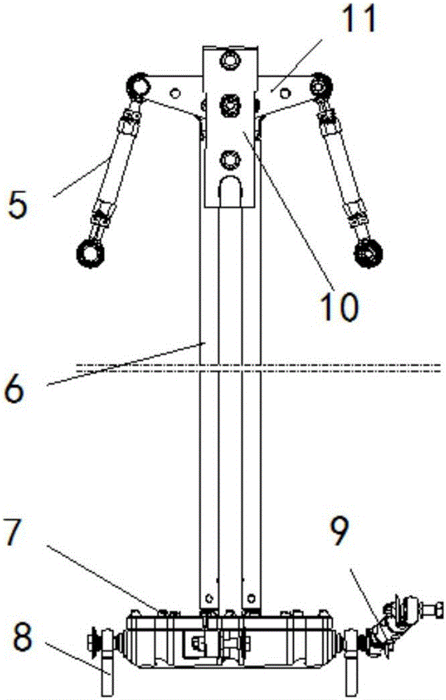
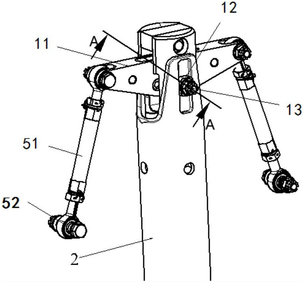
The invention discloses an intra-shaft operation rotor wing device, and belongs to the technical field of controlling rotor wings of helicopters. The intra-shaft operation rotor wing device comprises a rotating ring and fixed ring component, an anti-twist pull rod component, a steering engine, a support component, an upper collective pitch slide block, a lower collective pitch slide block, an upper collective pitch bolt, a lower collective pitch bolt, and a variable-torque pull rod component, wherein the variable-torque pull rod component is fixed on a main rotor wing shaft by virtue of the upper collective pitch bolt and the upper collective pitch slide block, and the upper collective pitch slide bock is inlaid at the upper end of the main rotor wing shaft and can slide up and down; the rotating ring and fixed ring component is fixed at the lower end of the main rotor wing shaft by virtue of the lower collective pitch bolt and the lower collective pitch slide block, and the lower collective pitch slide block is inlaid at the lower end of the main rotor wing shaft and can slide up and down; and the rotating ring and fixed ring component is arranged at the lower part of a main speed reducer and is connected with a rotor wing propeller hub by virtue of the variable-torque pull rod component, and the anti-twist pull rod component and the steering engine are fixed on the rotating ring and fixed ring component. The intra-shaft operation rotor ring device disclosed by the invention adopts an intra-shaft operation transmission mode to reduce sizes and weights of components, and is also beneficial for reducing flight resistance of a helicopter.

Description

technical field [0001] The invention belongs to the technical field of helicopter rotor control, and in particular relates to an in-axis control rotor device. Background technique [0002] Rotor control is an extremely important part of the helicopter rotor system. It mainly transmits the collective pitch and periodic pitch control input from the steering gear to the rotor blades to realize the change of the angle of attack of the blades, thereby controlling the magnitude and direction of the rotor lift and realizing Attitude control of the helicopter. [0003] The typical structure of the rotor control is mainly a ring-type spherical hinge structure, which is mainly composed of a moving ring and a fixed ring assembly, a large bearing, a large ball hinge assembly, a torque arm assembly, an anti-twist arm assembly, and a variable pitch rod assembly. The moving ring and the fixed ring assembly can slide up and down along the guide cylinder fixed on the upper end of the main r...

Claims


Application Information

Patent Timeline
Patent Type & Authority Applications(China)
IPC IPC(8): B64C27/59
CPCB64C27/59
Inventor 李永鑫郑俊伟董锦山彭利乐陆裕辉杨广勇潘柱金王健刘伟友李磊王洁
Owner CHINA HELICOPTER RES & DEV INST
Learn More