
Iron shell riveting method

An iron shell and riveting technology, applied in metal processing equipment, feeding devices, positioning devices, etc., can solve the problems of unsatisfactory product processing applicability, low production efficiency, high labor cost, etc., to improve production efficiency and processing accuracy , Improve the effect of processing applicability

Active Publication Date: 2017-03-08
GUANGDONG SHUOTAI INTELLIGENT EQUIP
View PDF11 Cites 1 Cited by
  • Summary
  • Abstract
  • Description
  • Claims
  • Application Information

AI Technical Summary

Problems solved by technology

[0002] At present, the riveting technology in industrial production requires manual bending of the required spare parts, and then accurately positioning the riveting hole, and then riveting by manual operation. This mode of operation, It has many processes, low production efficiency, high labor cost, and poor product consistency. It cannot be put into mass production well, and the quality cannot be guaranteed.
Although the semi-automated production of iron shell riveting has been realized, the processing of the product is relatively simple, and the processing applicability to meet the diversification of products is not satisfied.

Method used


Image

  • Iron shell riveting method
  • Iron shell riveting method

Examples


Embodiment Construction

[0025] The present invention will be further described below in conjunction with the accompanying drawings and embodiments.

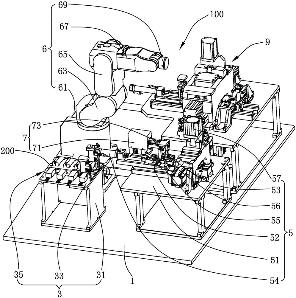
[0026] see figure 1 , a schematic diagram of the three-dimensional structure of the iron shell riveting machine provided for the invention. The iron shell riveting machine 100 is used for riveting the iron shell 200, including a frame 1 and a fixed seat 3 respectively fixed on the frame 1, a first riveting mechanism 5, a manipulator 6, a turning mechanism 7 and the second riveting mechanism 9.

[0027] The fixed seat 3 is used to install the iron shell 200, which includes a seat body 31, a plurality of sliding blocks 33 arranged at intervals above the seat body 31, and two adjacent sliding blocks 33. Between the sliding groove 35, the iron shell 200 is partially embedded in the sliding groove 35 and can move along the extending direction of the sliding groove 35.

[0028] The first riveting mechanism 5 is used for bending and riveting the reverse sid...


PUM


Abstract

The invention discloses an iron shell riveting method. The iron shell riveting method is used for riveting machining of an iron shell and comprises the following steps that the iron shell is placed on a fixed seat, the iron shell is grabbed to a first riveting mechanism by a manipulator, and the back face of the iron shell is bended and riveted by the first riveting mechanism; the iron shell with a riveted back face is grabbed to a turnover mechanism by the manipulator, and the turnover mechanism grabs the iron shell transferred by the manipulator and turns over 180 degrees; and the iron shell is grabbed to a second riveting mechanism by the manipulator from the turnover mechanism, and the front face of the iron shell is bended and riveted. According to the iron shell riveting method, the back face and the front face of the iron shell are bended and riveted by the first riveting mechanism and the second riveting mechanism in sequence, so that the upgrade of iron machining from manual work to automatic production is achieved, and production efficiency and machining precision are improved.

Description

technical field [0001] The invention relates to the technical field of automation equipment, in particular to an iron shell riveting method. Background technique [0002] At present, the riveting technology in industrial production requires manual bending of the required spare parts, and then accurately positioning the riveting hole, and then riveting by manual operation. This mode of operation, It has many processes, low production efficiency, high labor cost, and poor product consistency. It cannot be put into mass production well, and its quality cannot be guaranteed. Although the semi-automation of iron shell riveting production has been realized at present, the processing of the product is relatively simple, and it does not meet the processing applicability of product diversification. [0003] Therefore, it is necessary to provide a new iron shell riveting machine to solve the above problems. Contents of the invention [0004] In order to solve the above technical p...

Claims


Application Information

Patent Timeline
Patent Type & Authority Applications(China)
IPC IPC(8): B21D39/00B21D43/00B21D43/10
CPCB21D39/00B21D43/003B21D43/105
Inventor 张帆
Owner GUANGDONG SHUOTAI INTELLIGENT EQUIP
Learn More