Air bearing

A stage and air flotation technology, which is applied in the direction of instruments, measuring instrument components, measuring devices, etc., can solve the problems of uneven flow rate at the air outlet, difficult level effect of the substrate, etc.

Active Publication Date: 2020-02-07
UTECHZONE CO LTD
View PDF14 Cites 0 Cited by
  • Summary
  • Abstract
  • Description
  • Claims
  • Application Information

AI Technical Summary

Problems solved by technology

However, most of the air flotation platforms currently used in the industry need to control the flow of each air outlet through multiple air inlets and multiple throttle valves, and most of the current air flotation platforms have the problem of uneven flow at the air outlets, making It is difficult to maintain the level effect of the substrate for precise inspection

Method used


Image

  • Air bearing
  • Air bearing
  • Air bearing

Examples


Embodiment Construction

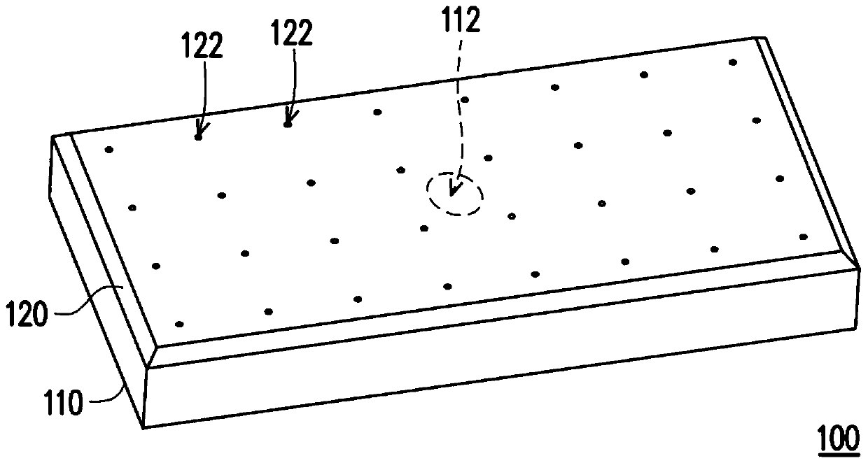
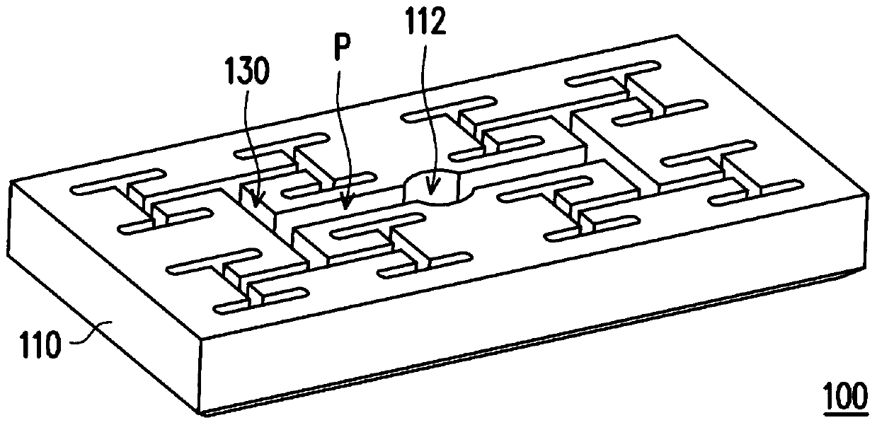
[0025] figure 1 is a schematic diagram of an air bearing platform according to an embodiment of the present invention. figure 2 yes figure 1 A partial schematic diagram of the air bearing platform. Please refer to figure 1 and figure 2 , in this embodiment, the air bearing platform 100 includes a bottom layer 110 , a top layer 120 and an air chamber 130 . The bottom layer 110 has an air inlet 112 . The top layer 120 is disposed above the bottom layer 110 and has a plurality of air outlets 122 . The air chamber 130 is located between the top layer 120 and the bottom layer 110 , and communicates with the air inlet 112 on the bottom layer 110 and the air outlet 122 on the top layer 120 . For example, in this embodiment, the air chamber 130 is fabricated on the bottom layer 110 (such as figure 2 shown), but in other non-illustrated embodiments, the air chamber 130 can also be fabricated on the top layer 120 , or be fabricated in another layer member between the top layer...


PUM


Abstract

The invention provides an air floating carrying platform comprising a bottom layer, a top layer, and an air chamber. The bottom layer has an air inlet. The top layer is located above the bottom layer and has 2n air outlets. The air chamber is located between the top and bottom layers and has 2n airflow paths, where n is a positive integer. The airflow paths and the air outlets are arranged symmetrically on opposite sides of the air inlet. The air inlet is connected to the air outlets through the airflow paths, and the lengths of the air flow paths are equal. The air floating carrying platform provided by the invention is adapted to provide an airflow carrying substrate having a uniform flow rate and to maintain a horizontal effect of the substrate.

Description

technical field [0001] The present invention relates to a testing platform, and in particular to an air bearing platform for testing. Background technique [0002] In recent years, with the increasingly developed technology industry, electronic products have frequently appeared in daily life. Among them, the precision of parts used in electronic products is also a major consideration. Therefore, related detection instruments will be produced accordingly. For example, inspection instruments for inspecting substrates (such as glass) or other objects to be inspected usually need to be equipped with a stage, so that the substrate is arranged on the stage for related inspection. However, if the substrate is directly placed on the stage so as to be in direct contact, the substrate is likely to be damaged. Therefore, part of the current practice is to manufacture the stage as an air-floating stage on which the substrate is suspended. [0003] Furthermore, the air bearing platfo...

Claims


Application Information

Patent Timeline
Patent Type & Authority Patents(China)
IPC IPC(8): G01D11/00
CPCG01D11/00
Inventor 祁树泰
Owner UTECHZONE CO LTD
Why Eureka
Try Eureka