
Shell structure of mobile power source

A shell structure, mobile power technology, applied in the direction of collectors, electric vehicles, electrical components, etc., can solve the problems of mobile power damage, large power consumption, safety hazards, etc., to improve the anti-shock and anti-fall performance, the structure is reasonable and practical , the effect of improving the service life

Pending Publication Date: 2017-02-22
JIANGMEN HONGYI BATTERY
View PDF0 Cites 0 Cited by
  • Summary
  • Abstract
  • Description
  • Claims
  • Application Information

AI Technical Summary

Problems solved by technology

[0002] With the development of science and technology, mobile phones are becoming more and more intelligent, and various tablet computers are also emerging in an endless stream. Smart electronic devices have gradually become an indispensable part of people's lives; but usually, the smarter the electronic device, the more The greater the power consumption, resulting in insufficient battery life, so there are mobile power products to meet the needs at any time
The existing mobile power supply casing structure usually only has two left and right casings made of plastic material, which are connected as a whole by buckles. The mobile power supply casing with this structure is prone to the problem of buckle breaking when it falls, so This makes the anti-seismic and anti-drop performance poor, which brings great safety hazards to the use of the product, and after the buckle is broken, the shell cannot be reassembled, which may easily lead to damage to the mobile power supply

Method used


Image

  • Shell structure of mobile power source
  • Shell structure of mobile power source
  • Shell structure of mobile power source

Examples


Embodiment Construction

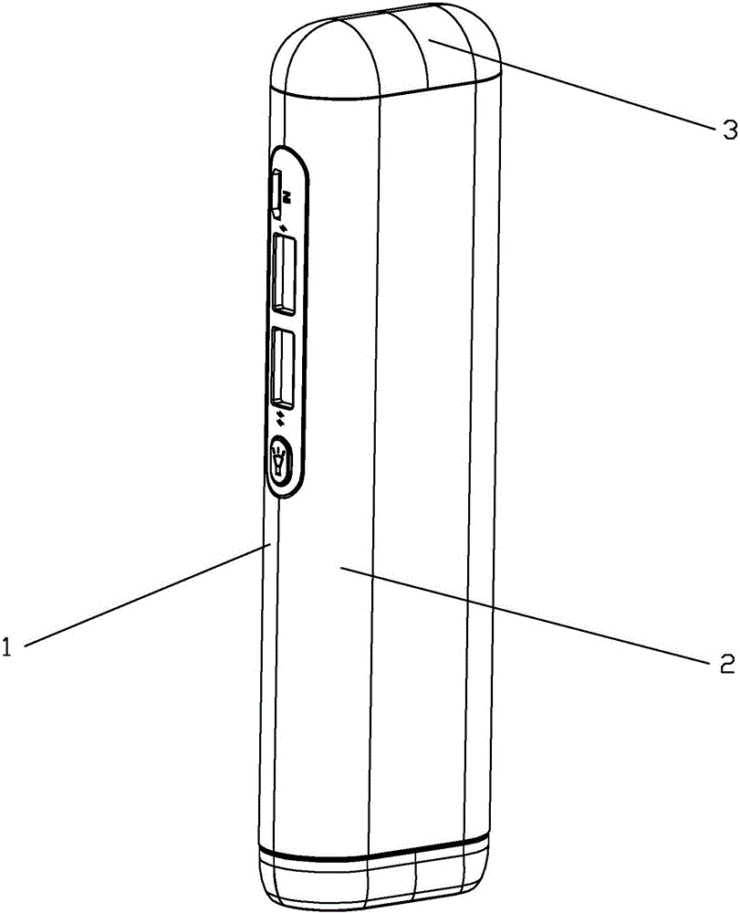
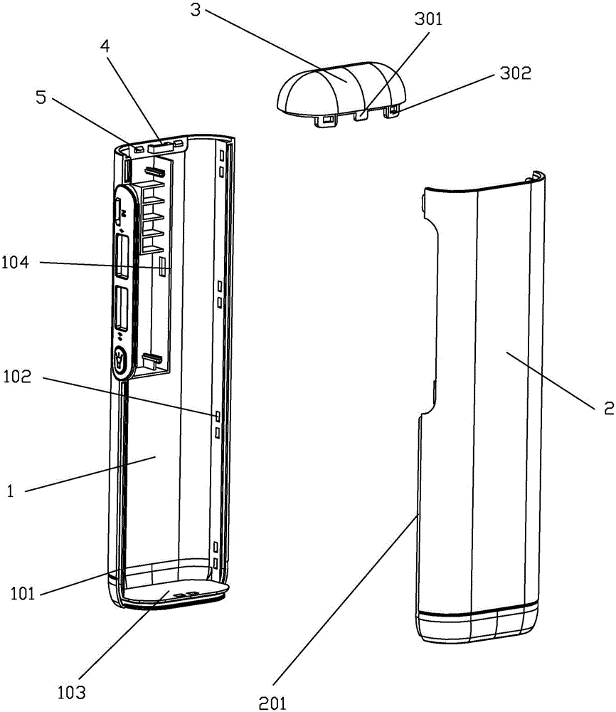
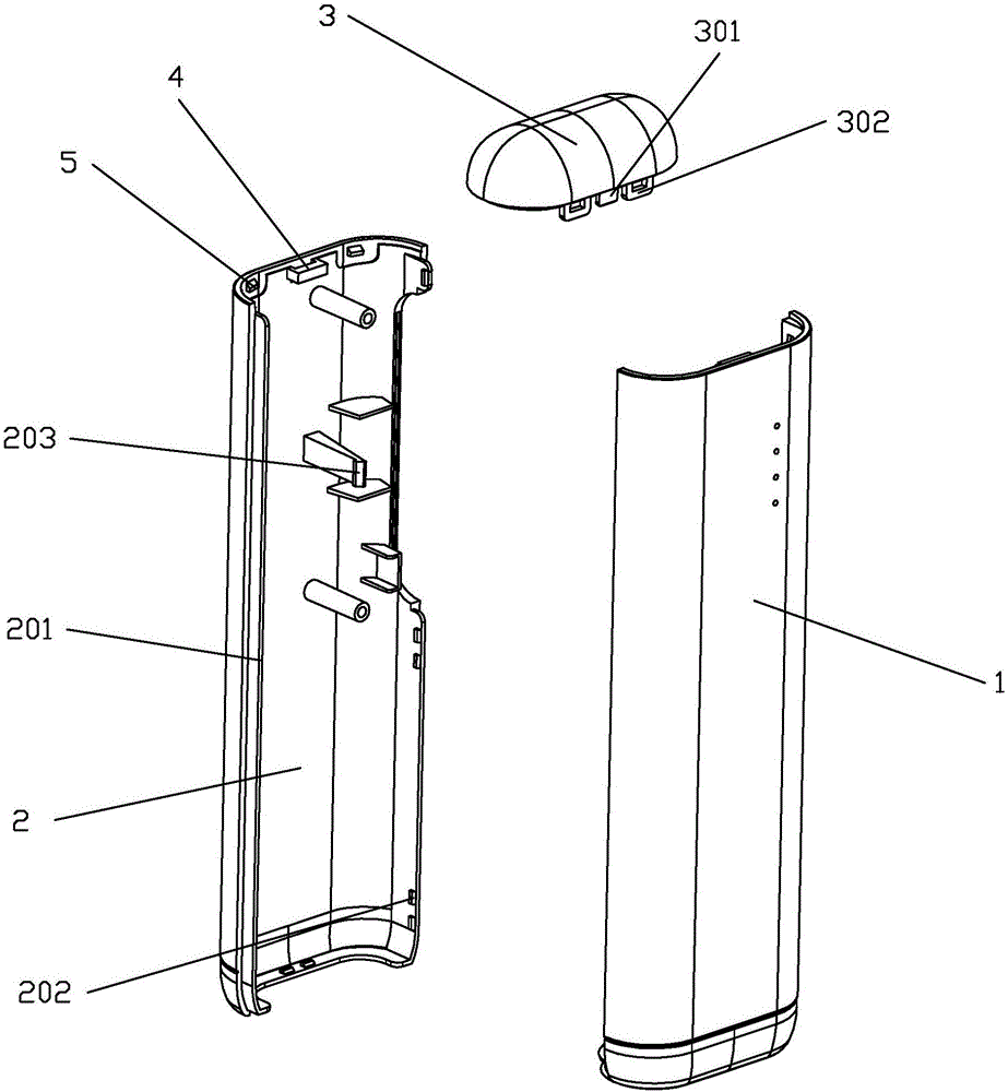
[0016] refer to Figure 1~Figure 5 , a shell structure of a mobile power supply, including a left half shell 1, a right half shell 2 and an upper cover 3, the left half shell 1 and the right half shell 2 are assembled into a shell, and a battery for installing a battery is formed in the shell And the inner cavity of the circuit board, the upper cover 3 is installed on the upper end of the shell; the edge of the left half shell 1 is provided with a positioning slot 101, and the edge of the right half shell 2 is provided with a positioning slot 101 Matching tongue 201, the inner side wall of the tongue 201 is provided with several buckle bosses 202, and the inner side wall of the positioning slot 101 is provided with a bayonet matching with the buckle bosses 202 102, a sealing strip is installed in the positioning slot 101; two tongue plates 103 are arranged at the lower end of the left half shell 1, and the two tongue plates 103 are stacked to form the positioning slot 101, the...


PUM


Abstract

The invention discloses a shell structure of a mobile power source. The shell structure comprises a left half shell, a right half shell and an upper cover. The left half shell and the right half shell can be assembled to obtain an outer shell, an inner cavity for mounting batteries and circuit boards is formed in the outer shell, and the upper cover is mounted at the upper end of the outer shell; a positioning slot is formed in an edge of the left half shell, a tongue which is matched with the positioning slot is arranged at an edge of the right half shell, a plurality of clip bosses are arranged on the inner side wall of the tongue, bayonets which are matched with the clip bosses are arranged on the inner side wall of the positioning slot, and sealing adhesive strips are mounted in the positioning slot; two tongue plates are arranged at the lower end of the left half shell and are stacked on each other to form the positioning slot, and the widths of the tongue plates are consistent with the outer shell. The shell structure has the advantages of firmness and reliability.

Description

technical field [0001] The invention relates to the field of mobile power sources, in particular to a housing structure of the mobile power source. Background technique [0002] With the development of science and technology, mobile phones are becoming more and more intelligent, and various tablet computers are also emerging in an endless stream. Smart electronic devices have gradually become an indispensable part of people's lives; but usually, the smarter the electronic device, the more The power consumption is also greater, resulting in insufficient battery life, so mobile power products have appeared to meet the needs at any time. The existing mobile power supply casing structure usually only has two left and right casings made of plastic material, which are connected as a whole by buckles. The mobile power supply casing with this structure is prone to the problem of buckle breaking when it falls, so This makes the anti-seismic and anti-drop performance poor, which brin...

Claims


Application Information

Patent Timeline
Patent Type & Authority Applications(China)
IPC IPC(8): H02J7/00
CPCH02J7/0042
Inventor 杨长明
Owner JIANGMEN HONGYI BATTERY
Learn More