
Parallel type six-freedom-degree redundant driving antenna structural system

A technology for driving antennas and degrees of freedom, applied in the directions of antennas, antennas, antenna supports/installation devices suitable for movable objects, etc., can solve the problems of inability to achieve negative angle pitch, and the "blind area of ​​the antenna base over the top", achieving Reduce singular shape, reduce weight, and achieve the effect of negative angle pitch

Active Publication Date: 2017-02-22
NO 54 INST OF CHINA ELECTRONICS SCI & TECH GRP
View PDF4 Cites 10 Cited by
  • Summary
  • Abstract
  • Description
  • Claims
  • Application Information

AI Technical Summary

Problems solved by technology

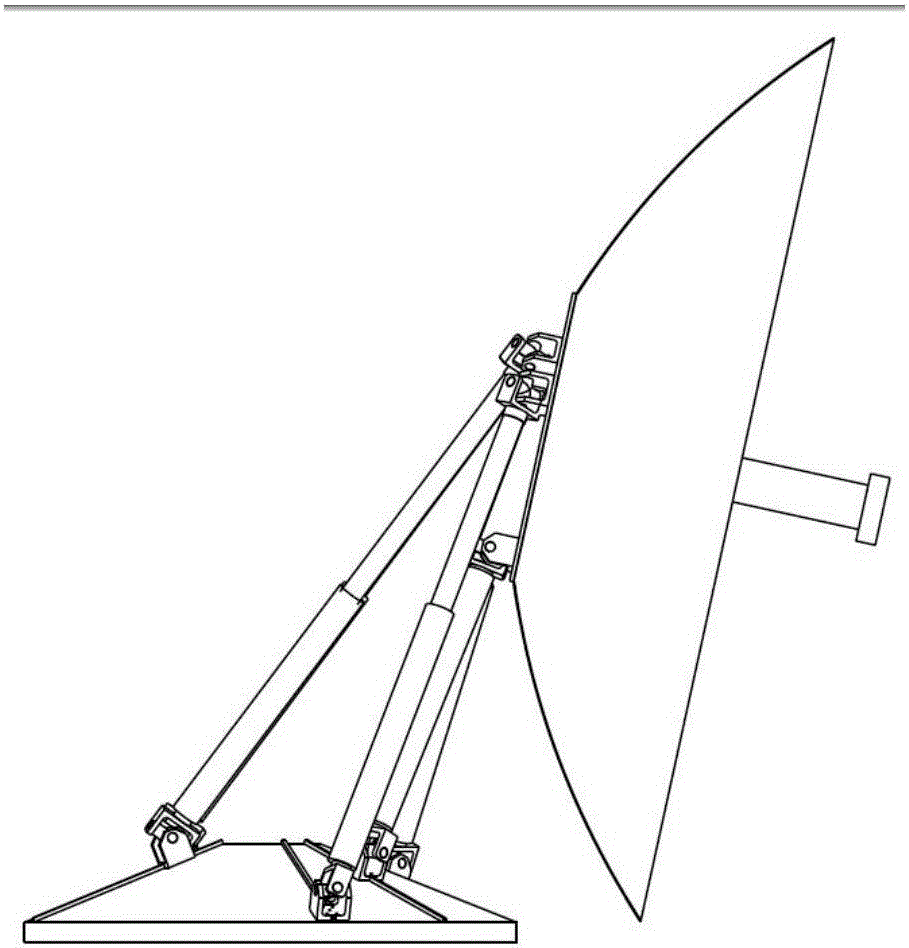
[0004] In view of the many shortcomings of the traditional antennas mentioned above, a parallel six-degree-of-freedom redundant drive antenna structure system is provided, which solves the problem of the "blind area" of the traditional antenna seat over the top, and solves the problem that the traditional Stewart type parallel structure cannot Realize the problem of negative angle pitch, realize the continuous tracking of any attitude and no blind zone in the antenna working airspace, improve the stability and rapidity of the system, and reduce the weight of the entire antenna system

Method used


Image

  • Parallel type six-freedom-degree redundant driving antenna structural system
  • Parallel type six-freedom-degree redundant driving antenna structural system
  • Parallel type six-freedom-degree redundant driving antenna structural system

Examples


Embodiment Construction

[0025] The present invention will be described in further detail below in conjunction with accompanying drawing:

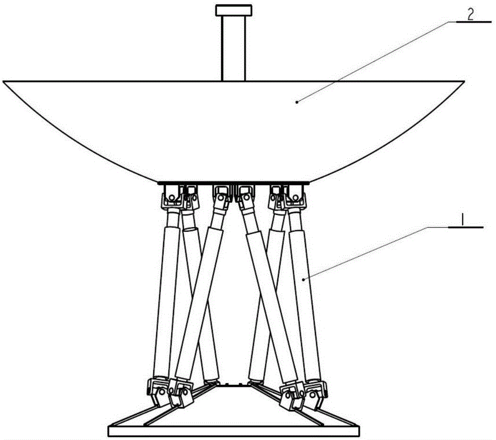
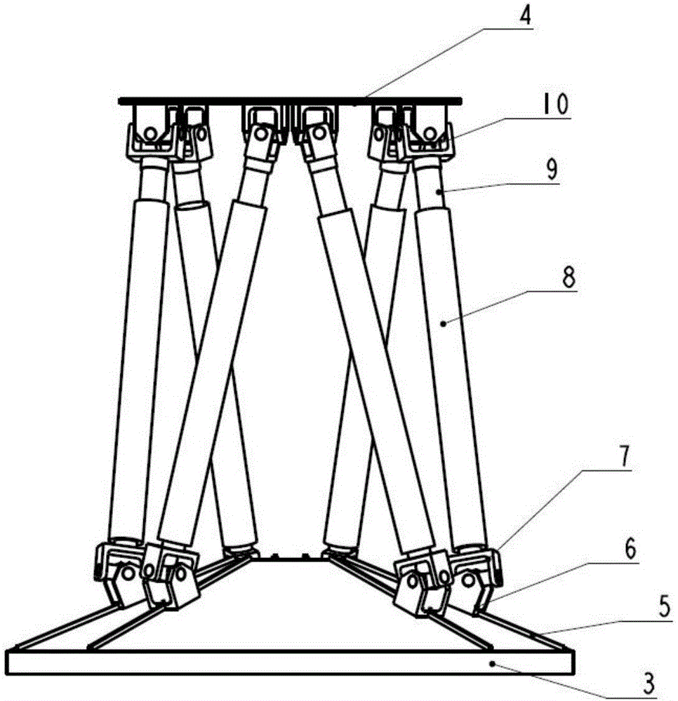
[0026] Such as figure 1 , 2 As shown, a ship-borne parallel six-degree-of-freedom redundant drive antenna structure system includes an antenna reflector 2, and the antenna emitter 2 is connected to the antenna base 1, and the antenna base includes a fixed platform 2 and a moving Platform 4, the fixed platform 3 is fixed on a certain plane, and the moving platform 4 is arranged in parallel above the fixed platform 3. The fixed platform 3 is in the shape of a conical cone with a gradually reduced diameter and raised, and is evenly distributed on the outer peripheral surface of the fixed platform. There are three sets of guide rail units, and the three sets of guide rail units are evenly arranged on the fixed platform. Each set of guide rail units is composed of two guide rails forming a certain angle. The range of the included angle is (0-30°], and each guide rail ...


PUM


Abstract

Disclosed is a parallel type six-freedom-degree redundant driving antenna structural system. The parallel type six-freedom-degree redundant driving antenna structural system comprises an antenna reflective surface and an antenna pedestal, wherein the antenna reflective surface is linked on the antenna pedestal; the antenna pedestal comprises a fixed platform and a movable platform which are arranged in parallel; the fixed platform is a convex circular table with gradually decreased caliber; three groups of guiding rail units are uniformly distributed on the fixed platform; each guiding rail unit group consists of two guiding rails; each guiding rail is equipped with a driving sliding block; a telescopic unit is hinged on each driving sliding block in a one-to-one correspondence manner; all the telescopic units are hinged to the movable platform; each movement point can perform coordination action by following four movement units, so that special forms and positions can be effectively reduced; the convex circular table shape of the fixed platform is matched with the driving sliding blocks to realize overturn of the antenna; the multiple driving sliding blocks are matched with the telescopic units to perform a coordination operation, so that not only all-around tracking of the antenna, but also negative angle pitching of the antenna can be realized; and consequently, the stability, flexibility and rigidity of the mechanism are highly reinforced.

Description

technical field [0001] The invention belongs to the field of ship-borne antenna devices, and in particular relates to a parallel six-degree-of-freedom redundant driving antenna structure system. Background technique [0002] The antenna pedestal is the support and orientation device of the antenna, which is used to enable the antenna to accurately point to the target according to the predetermined trajectory or follow the target movement, and quickly and accurately follow the target movement. Its structure affects the whole antenna to a large extent. performance indicators. [0003] With the continuous development of antenna technology, especially the rapid development of mobile carrier antenna equipment, the performance requirements for antenna equipment such as rotational angular velocity, angular acceleration, accuracy, stiffness, reliability, and dynamic characteristics are increasing, while the performance indicators of traditional antenna bases It has become increasin...

Claims


Application Information

Patent Timeline
IPC IPC(8): H01Q1/12H01Q1/34H01Q3/08
CPCH01Q1/12H01Q1/34H01Q3/08Y02D30/70
Inventor 段艳宾窦玉超付强李建军张文静
Owner NO 54 INST OF CHINA ELECTRONICS SCI & TECH GRP
Learn More