First stage reentry control system and method of launch vehicle, simulation system and method
A technology for a launch vehicle and a control system, which is applied in the field of a sub-stage reentry control system of a launch vehicle and a simulation system, can solve problems such as hidden safety hazards, difficulty in search and recovery, and easy disassembly, and achieve good aerodynamic characteristics and good control characteristics. The effect of the deceleration characteristics and the high accuracy of the landing zone
- Summary
- Abstract
- Description
- Claims
- Application Information
AI Technical Summary
Problems solved by technology
Method used
Image
Examples
Embodiment 1
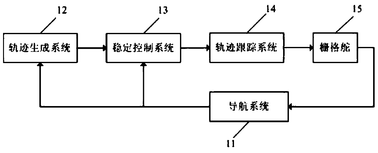
[0056] This embodiment describes in detail the re-entry control system of the first sub-stage of the launch vehicle of the present invention. A cabin section is expanded at the head of the first sub-stage of the launch vehicle, and the re-entry control system is installed in the extended cabin section. Its structural diagram is as follows figure 1 As shown, it includes: a grid rudder 15 and a grid rudder control system. The grid rudder control system is used to control the re-entry flight attitude of the grid rudder, and then control the re-entry flight attitude of the first sub-stage of the launch vehicle.
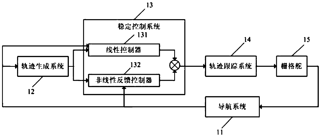
[0057] In the present embodiment, the grid rudder control system includes: navigation system 11, trajectory generation system 12, stability control system 13 and trajectory tracking system 14, navigation system 11 and grid rudder 15, stability control system 13 and trajectory generation system 12 respectively connected, the navigation system 11 is used to obtain the real-t...
Embodiment 2
[0069] This embodiment describes in detail the re-entry controller of the first sub-stage of the launch vehicle of the present invention, which is a re-entry control method realized by the first-sub-stage re-entry control system of the launch vehicle of Embodiment 1, which includes the following steps:
[0070] S11: the grid rudder control system produces the flight parameters of the reentry flight attitude of the control grid rudder;
[0071] S12: The grid rudder generates aerodynamic force, provides stable control force during the re-entry flight according to the flight parameters, and drives the re-entry flight of the first sub-stage of the launch vehicle.
[0072] Wherein, step S11 specifically includes:
[0073] S111: The navigation system measures the real-time flight parameters of the grid rudder, and transmits the real-time flight parameters to the trajectory generation system and the stability control system;
[0074] S112: The trajectory generation system receives t...
Embodiment 3
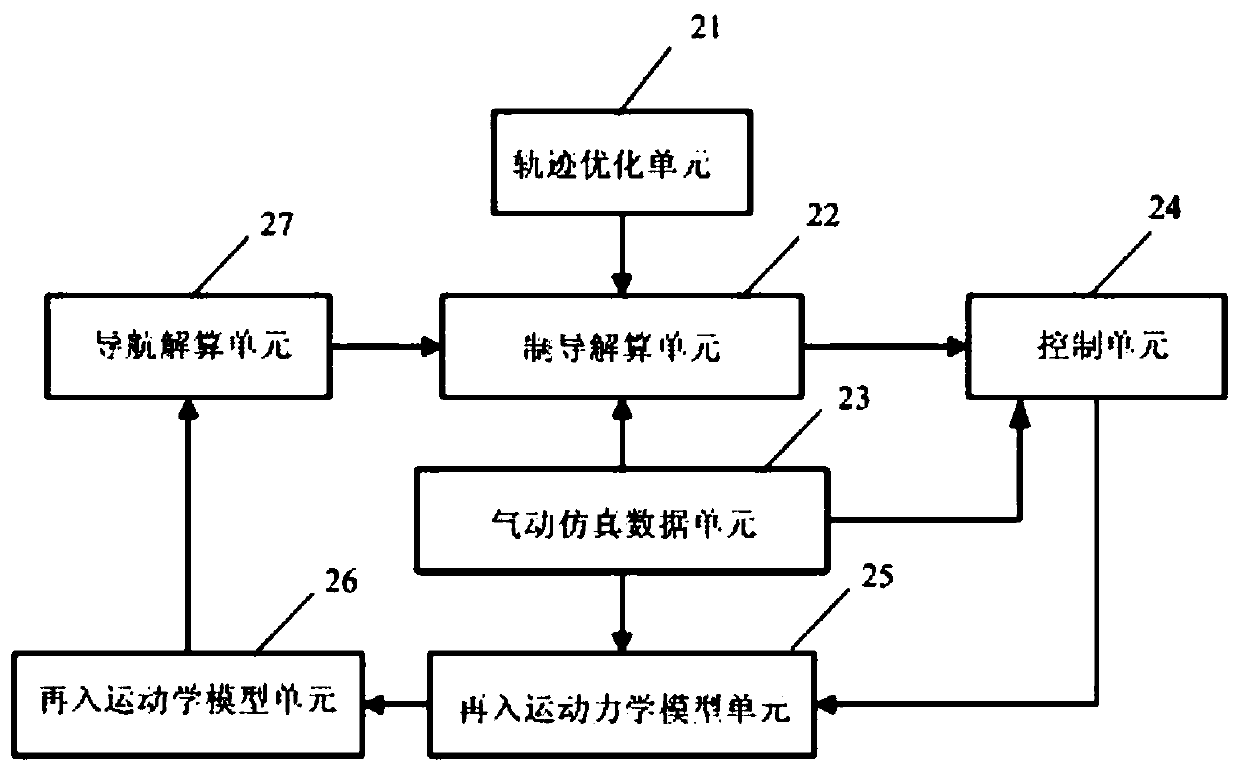
[0078] This embodiment describes in detail the first sub-stage reentry simulation system of the launch vehicle of the present invention, and its structural schematic diagram is as follows image 3 As shown, it includes: trajectory optimization unit 21, guidance calculation unit 22, aerodynamic simulation data unit 23, control unit 24, re-entry kinematics model unit 25, re-entry kinematics model unit 26 and navigation calculation unit 27, wherein , the trajectory optimization unit 21 is connected with the guidance calculation unit 22, and is used to provide the guidance calculation unit 22 with a reentry trajectory through ballistic optimization; The model unit 25 is connected to provide aerodynamic data for the guidance calculation unit 22, the control system 24 and the reentry kinematics model unit 25; the guidance calculation unit 22 is connected to the control system 24 for solving Calculate the outer loop slow loop rudder control amount, and transmit it to the control syst...
PUM
 Abstract
Description
Claims
Application Information
 - R&D
- Intellectual Property
- Life Sciences
- Materials
- Tech Scout
- Unparalleled Data Quality
- Higher Quality Content
- 60% Fewer Hallucinations
Browse by: Latest US Patents, China's latest patents, Technical Efficacy Thesaurus, Application Domain, Technology Topic, Popular Technical Reports.
© 2025 PatSnap. All rights reserved.Legal|Privacy policy|Modern Slavery Act Transparency Statement|Sitemap|About US| Contact US: help@patsnap.com


