


Quick Research
Generate reliable direction feasibility study reports for your R&D in just a few steps.

Technical Q&A
Discover and master advanced knowledge NOW. Basics, ideas, possibilities, all at once.

Find Solutions
As an expert in R&D theories, this can generate solutions to your technical problems instantly.

Evaluate Feasibility
Analyze your overall solution with one click, know your potential R&D risks in advance.

Monitor Landscape
Get weekly tech updates, stay abreast of the latest tech innovations and key insights.
Headset device
A head-mounted device and support technology, applied in the direction of optical components, optics, instruments, etc., can solve the problems of long time to adjust the length of the side strap, low wearing efficiency, long time to wear on the head, etc., and achieve simple operation , Improve wearing efficiency and shorten the time to wear on the head
- Summary
- Abstract
- Description
- Claims
- Application Information
AI Technical Summary
Problems solved by technology
Method used
Image

Examples
Embodiment 1
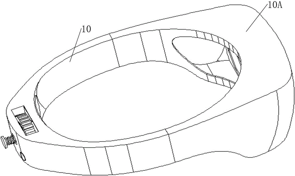
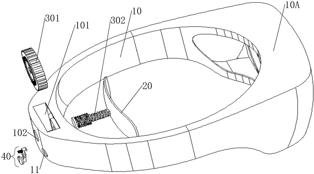
[0066] see figure 1 and figure 2 , in the first embodiment of the present invention, the support adjustment structure is specifically a rotating part 30, the rotating part 30 includes a first rotating part 301 and a rotating shaft 302, the first rotating part 301 is arranged at the rear of the headwear main body 10 In the cavity 101, the rotating shaft 302 is arranged in the through hole 102 at the rear of the headwear body 10, the first rotating member 301 is screwed to the rotating shaft 302, and the rotating shaft 302 is connected to the rear side support 20, wherein the cavity 101 is connected to the The through hole 102 communicates.
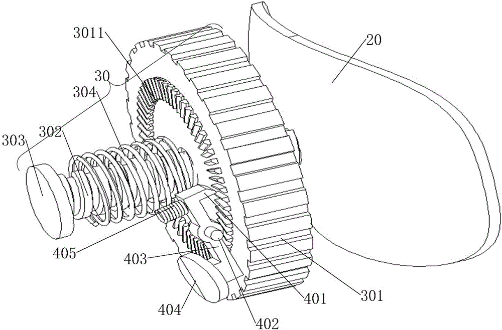
[0067] Specifically, see image 3 Since the first rotating member 301 is threadedly connected with the rotating shaft 302, turning the first rotating member 301 can make the rotating shaft 302 move along the front and rear directions of the headwear main body 10, thus the headwear can be adjusted by rotating the first rotating member 301...
Embodiment 2
[0084] see Figure 7 to Figure 11 , in the second embodiment of the present invention, the support adjustment structure is specifically the first push-pull part 50, the first push-pull part 50 includes a first push rod 502 and a first limit mechanism; the first push rod 502 is arranged on the head In the through hole 102 at the rear of the wearing body 10 , the front end of the first push rod 502 is connected to the rear support 20 ; the first limiting mechanism is connected to the first push rod 502 .
[0085] In the second embodiment of the present invention, the first push-pull part 50 also includes a first support frame 501, the first support frame 50 is arranged in the cavity 101 at the rear of the headwear body 10, and the first support frame 50 has a hollow structure 5011 , the hollow structure 5011 communicates with the through hole 102 and the cavity 101 respectively, and the through hole 102 communicates with the cavity 101 ;
[0086] Specifically, such as Figure ...
Embodiment 3
[0102] see Figure 12 to Figure 21 , in the third embodiment of the present invention, the support adjustment structure is specifically the second push-pull part 51 and the cross part 52, wherein the front end of the cross part 52 is connected to the rear support part 20, and its rear end is connected to the headwear main body 10; The second push-pull part 51 includes a second push rod 512 and a second limiting mechanism; the second push rod 512 is arranged in the first through hole 107 at the rear of the headwear body 10, and the cross part 521 of the cross part 52 is connected to the second The front end of the push rod 512 is connected; the second limiting mechanism is connected with the second push rod 512 .
[0103] In the third embodiment of the present invention, as Figure 13 and Figure 16 As shown, the second push-pull part 51 also includes a second support frame 511, the second support frame 511 is arranged in the cavity 101 at the rear of the headwear body 10, an...
PUM
 Abstract
Description
Claims
Application Information
 - R&D Engineer
- R&D Manager
- IP Professional
- Industry Leading Data Capabilities
- Powerful AI technology
- Patent DNA Extraction
Browse by: Latest US Patents, China's latest patents, Technical Efficacy Thesaurus, Application Domain, Technology Topic, Popular Technical Reports.
© 2024 PatSnap. All rights reserved.Legal|Privacy policy|Modern Slavery Act Transparency Statement|Sitemap|About US| Contact US: help@patsnap.com