Water-saving squatting pan

A technology for toilets and urinals, which can be used in flushing toilets, water supply devices, buildings, etc., and can solve problems such as large water consumption and inconvenient installation

Inactive Publication Date: 2017-02-22
XINGTAI YISHENGSHUI BATHROOM SCI & TECH CO LTD
View PDF7 Cites 1 Cited by
  • Summary
  • Abstract
  • Description
  • Claims
  • Application Information

AI Technical Summary

Problems solved by technology

[0004] In view of the above problems, the design of the present invention utilizes atmospheric pressure and water flow gravity to provide a water-saving toilet with flexible installation and increased siphon force, so as to solve the defects of inconvenient installation and large water consumption in the prior art

Method used


Image

  • Water-saving squatting pan
  • Water-saving squatting pan
  • Water-saving squatting pan

Examples


Embodiment 1

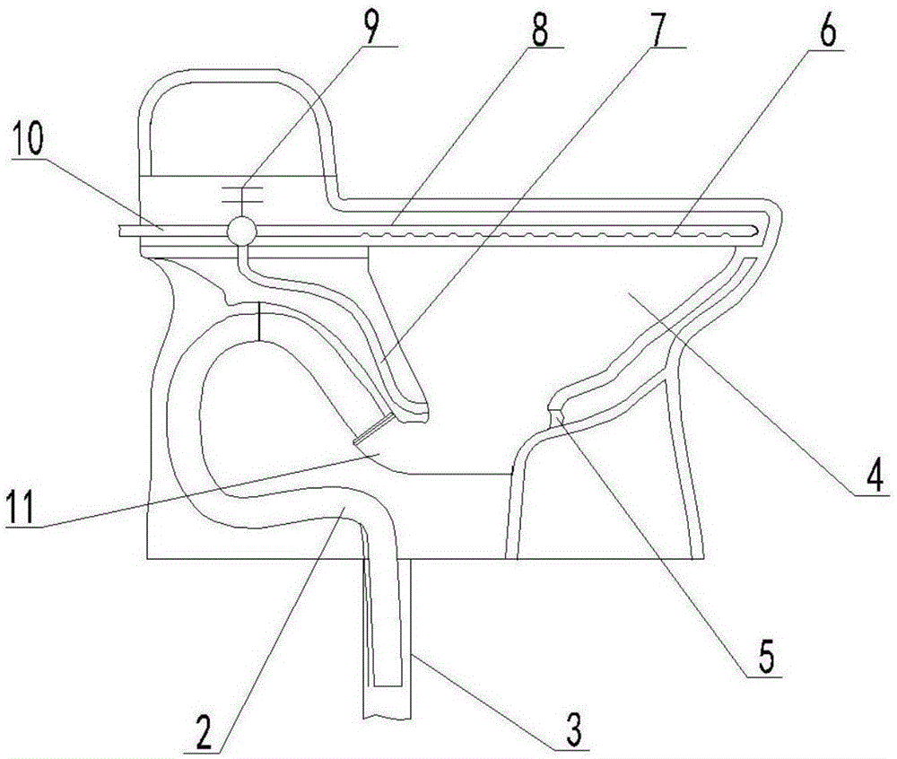
[0028] like figure 2 The structure of the present invention is applied to a tankless jetted toilet, which includes a urinal 4, a delay valve 9 connected to a water inlet pipe 10, and the water inlet pipe 10 is respectively connected to the upper part of the urinal 5 with a spray hole 6 along the mouth. The coil pipe 8, and the lower outlet pipe 7 connected with the jet port 5 at the lower part of the urinal 4.

[0029] The coil pipe 8 is arranged in the cavity of the upper edge of the urinal 4, which not only avoids the waste of filling all the cavity space when flushing in the prior art, but also reduces the pressure loss, so that the flushing force of the injection hole 6 is strong; The 5 position is facing the sewage outlet 11 at the bottom of the urinal 4, so that the water can directly flush the dirt into the sewage outlet 11 with a strong impulsive force.

[0030] When in use, the water can simultaneously flush the inner wall of the urinal 4 and wash away the dirt with...

Embodiment 2

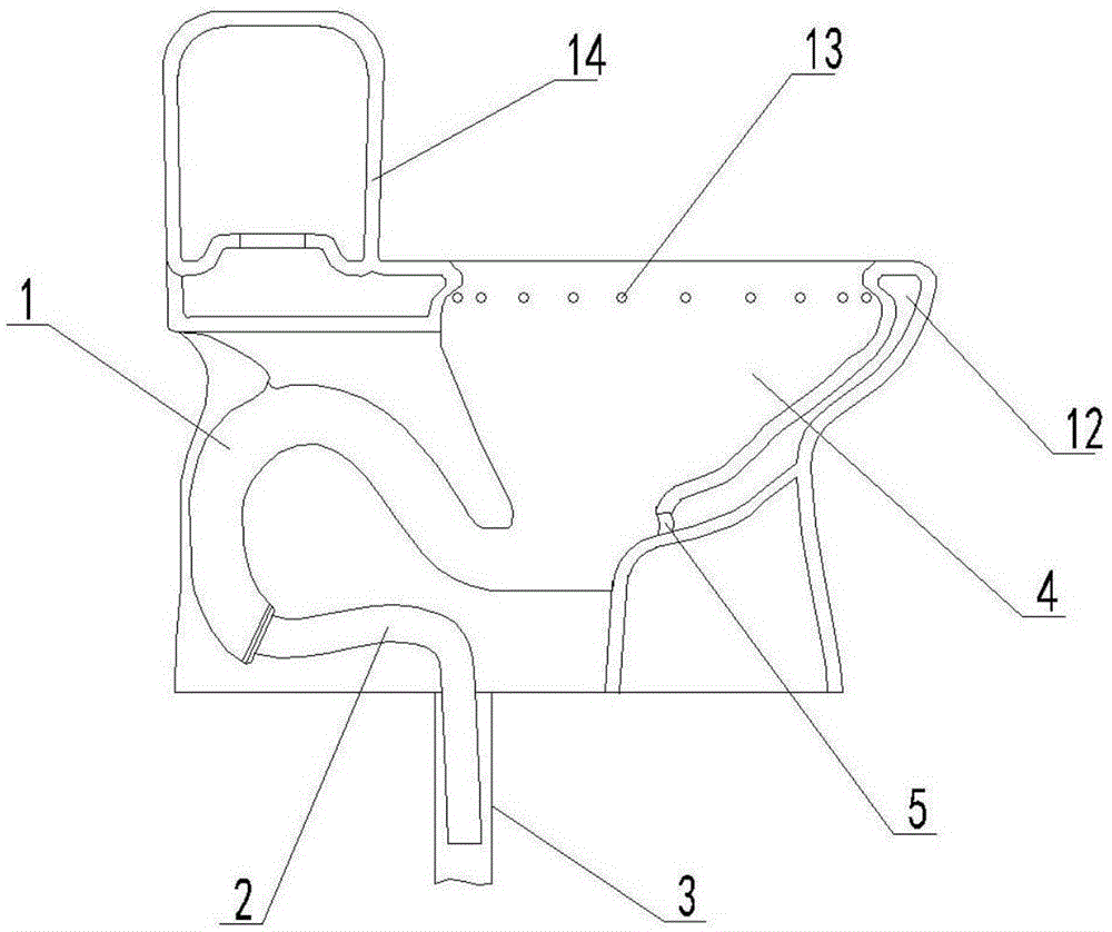
[0033] like image 3 The structure of the present invention is applied to a water tank type toilet, which includes a water inlet chamber 12 on the upper edge of the urinal 4, a flushing hole 13, and a jet port 5 connected to the water inlet chamber 12 at the lower part of the urinal 4. The cavity 12 communicates with the water tank 8 .

[0034] During use, the water in the water tank 14 passes through the water inlet chamber 12 to flush the urinal 4 inner wall and wash away the dirt through the flushing hole 13 and the injection port simultaneously. Due to the setting of the siphon hose 2, a larger siphon suction force can be produced, and the Dirt is pumped in the blowdown pipe 3.

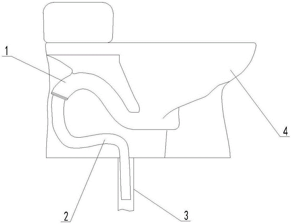
[0035] To sum up, the concept of the present invention is to install a siphon hose 2 at the bottom of the traditional toilet drain channel 1, changing the original mode where the toilet installation position must be determined according to the position of the drain pipe 3, so that the position of...


PUM

PropertyMeasurementUnit
The inside diameter ofaaaaaaaaaa
Lengthaaaaaaaaaa

Abstract

The invention belongs to bathroom devices and concretely relates to a water-saving squatting pan to solve deficiencies of inconvenient installation and great water use amount. The water-saving squatting pan comprises a urinal and a siphoning hose connected to the bottom of the urinal. The other end of the siphoning hose is provided with a spacing structure matching with a drain outlet. With the siphoning hose, an installation port of the squatting pan can be conveniently adjusted according to the position of the drain outlet and construction adjustments can be avoided; the siphoning hose can be inserted into the drain outlet, so pipe diameter and length can be rationally and properly prolonged and siphoning strength can be improved; and the water-saving squatting pan is advantaged by flexible and convenient installation, great siphoning strength, water use reduction and strong flushing and drain discharging strength.

Description

technical field [0001] The invention belongs to bathroom devices, in particular to a water-saving toilet. Background technique [0002] The bottom of the traditional toilet drains sewage through the sewage channel, and the fixed siphon force of the sewage outlet is small. During construction, the toilet needs to be installed according to the position of the sewage outlet. If the size of the toilet is not suitable, a large number of construction adjustments are required, which is extremely inconvenient. [0003] In addition, the siphon S-curve used in traditional toilet flushing must require a large amount of water to cooperate with the instantaneous flushing speed of the toilet to flush it clean. Generally, 6L or more water is consumed, and many of them cannot be rinsed clean once, and need to be flushed many times. Therefore there is the serious defect of water waste. Contents of the invention [0004] In view of the above problems, the present invention utilizes atmosp...

Claims


Application Information

Patent Timeline
IPC IPC(8): E03D11/18E03D11/02E03D11/13
Inventor 樊保山
Owner XINGTAI YISHENGSHUI BATHROOM SCI & TECH CO LTD
Why Eureka
Try Eureka