
Bridge and shear resistant combined structure thereof

A technology for combining structures and bridges, applied in the direction of bridges, bridge parts, bridge construction, etc., can solve problems such as reducing construction efficiency, overturning the bridge deck on the left and right sides of the bridge, weak bearing capacity of the stud shear key, etc.

Inactive Publication Date: 2017-02-22
GUANGDONG UNIV OF TECH
View PDF7 Cites 2 Cited by
  • Summary
  • Abstract
  • Description
  • Claims
  • Application Information

AI Technical Summary

Problems solved by technology

[0005] However, although it is simple and easy to achieve bridge shear resistance by means of stud shear keys, the bearing capacity of a single stud shear key is weak. In actual construction, it is often necessary to set a large number of stud shear keys. The combined action of two stud shear keys can provide sufficient shear resistance, which leads to an increase in construction cost and reduces construction efficiency.
At the same time, considering that the traffic lanes on the left and right sides of the bridge will be unbalanced due to the unbalanced force, the bridge will overturn on the left and right sides of the bridge. However, the stud shear keys in the prior art do not have the ability to resist pulling out and overturning.

Method used


Image

  • Bridge and shear resistant combined structure thereof

Examples


Embodiment Construction

[0023] The following will clearly and completely describe the technical solutions in the embodiments of the present invention with reference to the accompanying drawings in the embodiments of the present invention. Obviously, the described embodiments are only some, not all, embodiments of the present invention. Based on the embodiments of the present invention, all other embodiments obtained by persons of ordinary skill in the art without making creative efforts belong to the protection scope of the present invention.

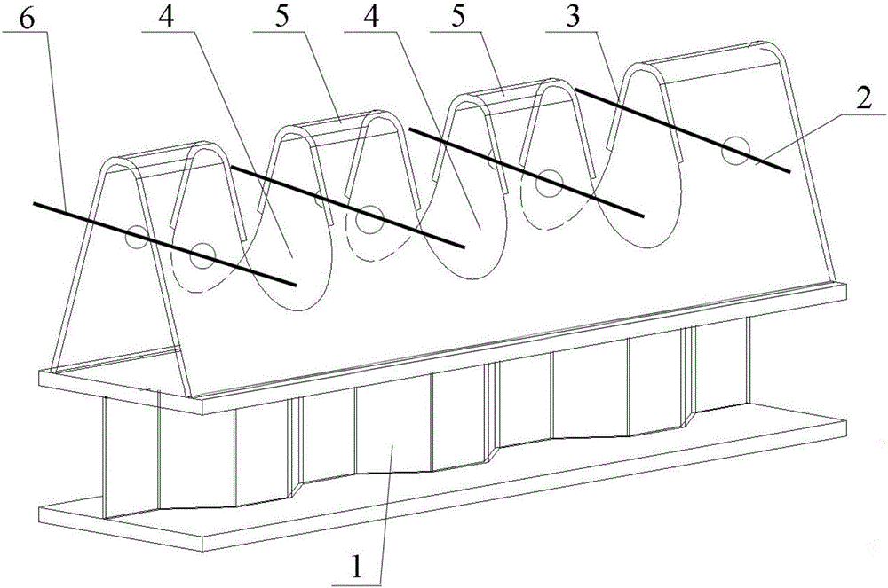
[0024] Please refer to figure 1 , figure 1 It is a schematic diagram of the overall structure of a specific embodiment provided by the present invention.

[0025] In a specific embodiment provided by the present invention, the shear composite structure of the bridge mainly includes a support structure 1 and a shear key.

[0026] Among them, the support structure 1 is generally used to bear the main load of the bridge, such as shear force and the like. In a ...


PUM

PropertyMeasurementUnit
Widthaaaaaaaaaa

Abstract

The invention discloses a shear resistant combined structure of a bridge. The shear resistant combined structure comprises a supporting structure and a shear key arranged on the supporting structure, wherein the shear key comprises a first shear resistant plate, second shear resistant plates and shearing rods; the top end of the first shear resistant plate and the top ends of the second shear resistant plates are mutually connected, and the bottom end of the first shear resistant plate and the bottom ends of the second shear resistant plates are respectively connected with two side edges of the supporting structure; each shearing rod laterally penetrates through the first shear resistant plate and the second shear resistant plates; a plurality of through holes allowing reinforced concrete to be embedded are formed in the first shear resistant plate and the second shear resistant plates; the first shear resistant plate and the second shear resistant plates form the shape of a triangle or a trapezoid, so that the structural shear resistant performance is greatly improved; the reinforced concrete is embedded by the through holes for resisting upward pulling force generated because the left side and the right side of the bridge are stressed unevenly; the shearing rods can strengthen the completeness of the combining of the shear key and the reinforced concrete, so that pulling resistant capacity and collapsing resistant capacity are effectively improved; and during construction, the construction cost can be reduced, and the construction efficiency can be improved. The invention also discloses the bridge comprises the shear resistant combined structure, and the bridge has the above beneficial effects.

Description

technical field [0001] The invention relates to the technical field of civil engineering, in particular to a shear-resistant combined structure of a bridge. The invention also relates to a bridge comprising the above-mentioned shear composite structure. Background technique [0002] With the development of Chinese society, more and more various engineering facilities have been widely used. [0003] In the field of bridge design, in order to adapt to different geographical environments and traffic needs, different types of bridges have been derived, such as girder bridges, arch bridges, rigid frame bridges, suspension bridges and cable-stayed bridges. The loads borne by the bridge structure are relatively comprehensive, among which the shear force is a relatively important part. The shear key is an important part of the bridge shear structure. Each part of the cross section can form a whole to bear the load. [0004] At present, the most widely used shear key is the stud s...

Claims


Application Information

Patent Timeline
IPC IPC(8): E01D19/00
CPCE01D19/00
Inventor 潘伟冯文贤
Owner GUANGDONG UNIV OF TECH
Learn More