
Sewing apparatus and automatic collection device thereof

A technology of automatic material collection and equipment, which is applied in the direction of clothing collection devices, sewing equipment, sewing machine components, etc., can solve the problems of taking up a lot of space, hurting people or objects, and danger, so as to improve the material receiving effect and simplify the mechanism Effect

Active Publication Date: 2017-02-22
SUZHOU HANDLEY ELECTROMECHANICAL TECH CO LTD
View PDF14 Cites 7 Cited by
  • Summary
  • Abstract
  • Description
  • Claims
  • Application Information

AI Technical Summary

Problems solved by technology

The inward-receiving structure is usually as follows: a base plate is set under the sewing area of ​​the machine head, a column is erected in the middle of the base plate, a cloth loading platform is arranged horizontally on the column, and two curved pipes are set on the bearing seat of the base plate. The root is the pressing rod, and the other is the receiving rod, and the two rods are pulled by the cylinder to move crosswise to realize the receiving process; this structure usually has the following defects. After the receiving is completed, the pressing rod and the receiving rod need to be moved open, which increases the complexity of the mechanism
In the outward-receiving structure, since the pressing rod and the receiving rod swing outward, on the one hand, it takes up more space, on the other hand, it is more dangerous, and there is a hidden danger of hurting people or objects

Method used


Image

  • Sewing apparatus and automatic collection device thereof
  • Sewing apparatus and automatic collection device thereof
  • Sewing apparatus and automatic collection device thereof

Examples


Embodiment Construction

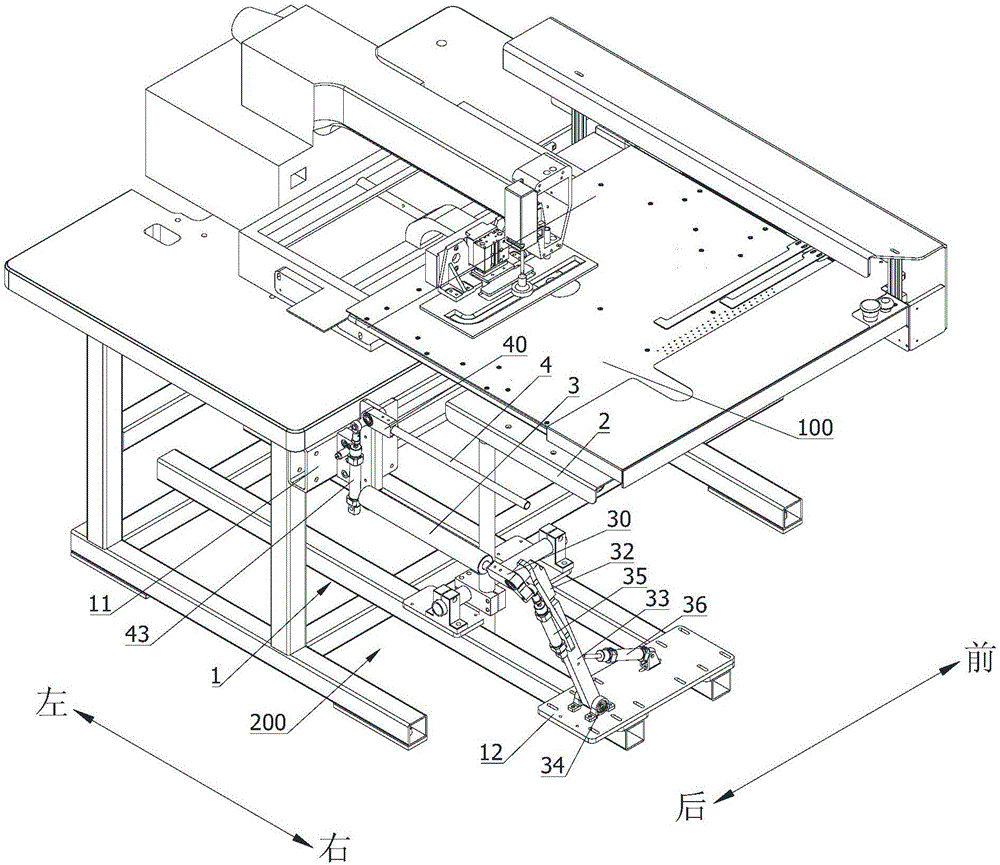
[0026] The preferred embodiments of the present invention will be described in detail below in conjunction with the accompanying drawings, so that the advantages and features of the present invention can be more easily understood by those skilled in the art. The definition of orientation in this paper is based on the usual observation angle of view of those skilled in the art and for the convenience of description. For example, the attached figure 1 in the manner indicated by each arrow in the , while "Up" corresponds to the figure 1 The upper side of the middle paper, "lower" corresponds to the attached figure 1 The lower side of the middle paper.

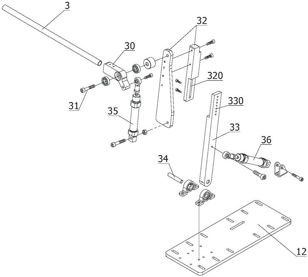
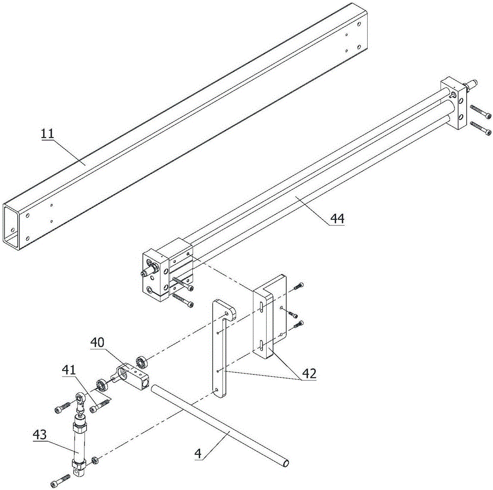
[0027] attached figure 1 Shown is a sewing device with an automatic material receiving device 200 of the present invention, such as a sewing machine capable of automatic material receiving. Refer to attached Figure 1-3 As shown, the automatic material receiving device 200 of the sewing equipment includes a frame 1, a cloth lo...


PUM


Abstract

The present invention discloses a sewing apparatus and an automatic collection device thereof. After collection, there can be no need to remove a press rod and a collection rod, so the structure is simplified. The sewing apparatus comprises a frame, a loading table, the press rod and the collection rod, the press rod is movably arranged on the frame through a material bearing base, and the collection rod is movably arranged on the frame through the material bearing base. The press rod is fixedly arranged on a press mounting seat, the press mounting seat is rotatably connected with the material bearing base through a first pivot, the axial line of the first pivot extends along the front and rear direction, the press rod is provided with a press position flush with the rear side of a cloth table, and a to-be-pressed position arranged on the left or right of the cloth table, and / or the press rod is fixedly arranged on a collection mounting seat. The collection mounting seat is rotatably connected with a collection bearing base through a second pivotal shaft, and the axis line of the second pivotal shaft extends along the front and back direction. The collection rod has a collection position higher than that of the cloth table and a to-be-collected position arranged on the left or right of the cloth table.

Description

technical field [0001] The invention relates to the field of sewing equipment, in particular to a sewing equipment and an automatic material receiving device thereof. Background technique [0002] In the prior art, after the cloth is sewn by sewing equipment such as a sewing machine, it needs to be collected. The receiving devices commonly used in existing sewing equipment can be roughly divided into inward receiving structures and outward receiving structures. The inward-receiving structure is usually as follows: a base plate is set under the sewing area of ​​the machine head, a column is erected in the middle of the base plate, a cloth loading platform is arranged horizontally on the column, and two curved pipes are set on the bearing seat of the base plate. The root is the pressing rod, and the other is the receiving rod, and the two rods are pulled by the cylinder to move crosswise to realize the receiving process; this structure usually has the following defects. After...

Claims


Application Information

Patent Timeline
Patent Type & Authority Applications(China)
IPC IPC(8): D05B41/00D05B29/00
CPCD05B29/00D05B41/00
Inventor 约翰·格瑞腾练伟峰
Owner SUZHOU HANDLEY ELECTROMECHANICAL TECH CO LTD
Learn More