
Device for conveying plastic test tubes

A technology for plastic test tubes and test tubes, applied in the field of analytical instruments, can solve problems such as unfavorable automation integration, stability, reliability and operational accuracy changes, and repetitive work.

Active Publication Date: 2017-02-22
JIANGSU SKYRAY INSTR
View PDF7 Cites 20 Cited by
  • Summary
  • Abstract
  • Description
  • Claims
  • Application Information

AI Technical Summary

Problems solved by technology

[0002] At present, in various analysis experiments, it is necessary to collect various types of samples for detection and analysis when performing various types of tests, and the test tubes are generally placed manually, and the repetitive work is not conducive to automation integration; There is a transmission test tube mechanism disclosed in the technology. The transmission mechanism consists of a chute for storing test tubes and a test tube output assembly formed by the cooperation of multiple conveying plates. It is not conducive to the integration of automation, and requires multiple collisions and guidance during the process of entering the blanking port, which can easily cause changes in the stability, reliability and operational accuracy of the test tube, and at the same time the efficiency is not high, so it is necessary to find a solution to this problem plan

Method used


Image

  • Device for conveying plastic test tubes
  • Device for conveying plastic test tubes
  • Device for conveying plastic test tubes

Examples


Embodiment Construction

[0039] Embodiments of the present invention are described in detail below, examples of which are shown in the accompanying drawings, wherein the same or similar reference numerals represent the same or similar elements or elements with the same or similar functions; The embodiments are exemplary and are only used to explain the present invention, but not to be construed as limiting the present invention.

[0040] In describing the present invention, it should be understood that the terms "upper", "lower", "bottom", "top", "front", "rear", "inner", "outer", "horizontal", " The orientation or positional relationship indicated by "vertical", etc. is based on the orientation or positional relationship shown in the drawings, which is only for the convenience of describing the present invention and simplifying the description, rather than indicating or implying that the device or element referred to must have a specific orientation, so as to Specific orientation configurations and ope...


PUM


Abstract

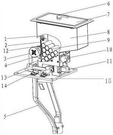
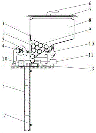
The invention discloses a device for conveying plastic test tubes. The device comprises a test tube bin, a carrying platform, a material distributing device and a test tube flow channel. An upper opening is formed in the upper portion of the test tube bin, and a cone-shaped bin and a test tube outlet connected with the cone-shaped bin are arranged on the lower portion of the test tube bin. The longitudinal dimension and the transverse dimension of the test tube outlet are matched with diameters and lengths of the test tubes. The carrying platform comprises a test tube gap and is located below the test tube bin, and the vertical height from the lower edge of the test tube outlet to the upper surface of the carrying platform is equal to or larger than the diameter of one test tube and smaller than the sum of the diameters of two test tubes. The material distributing device comprises a material distributing plate and is installed above the carrying platform, and the test tube flow channel comprises a flow channel opening and is installed below the carrying platform. According to the device for conveying the plastic test tubes, through cooperation of the test tube bin, the material distributing device and the test tube flow channel, the purposes that one test tube is output at one time and an opening of each test tube is upward are achieved, manual repeating labor is liberated, reliability and stability of test tube outputting are high, and external interference factors are less, so that the device for conveying the plastic test tubes has obvious advantages.

Description

technical field [0001] The invention belongs to the field of analytical instruments, in particular to a device for transporting plastic test tubes. Background technique [0002] At present, in various analysis experiments, it is necessary to collect various types of samples for detection and analysis when performing various types of tests, and the test tubes are generally placed manually, and the repetitive work is not conducive to automation integration; There is a transmission test tube mechanism disclosed in the technology. The transmission mechanism consists of a chute for storing test tubes and a test tube output assembly formed by the cooperation of multiple conveying plates. It is not conducive to the integration of automation, and requires multiple collisions and guidance during the process of entering the blanking port, which can easily cause changes in the stability, reliability and operational accuracy of the test tube, and at the same time the efficiency is not h...

Claims


Application Information

Patent Timeline
Patent Type & Authority Applications(China)
IPC IPC(8): B65G47/14B65G47/88
CPCB65G47/1407B65G47/8815B65G2203/0208
Inventor 应刚丁建峰邓东卫谢松林
Owner JIANGSU SKYRAY INSTR
Learn More