


Quick Research
Generate reliable direction feasibility study reports for your R&D in just a few steps.

Technical Q&A
Discover and master advanced knowledge NOW. Basics, ideas, possibilities, all at once.

Find Solutions
As an expert in R&D theories, this can generate solutions to your technical problems instantly.

Evaluate Feasibility
Analyze your overall solution with one click, know your potential R&D risks in advance.

Monitor Landscape
Get weekly tech updates, stay abreast of the latest tech innovations and key insights.
Ship-loaded thrown type radioactivity monitoring drifting buoy
A drifting buoy and radioactive technology, used in buoys, radiation intensity measurement, special-purpose ships, etc., can solve problems such as marine environmental impact, western Pacific pollution, etc., to enhance stability and reliability, reduce static power consumption, and improve measurement. The effect of precision
- Summary
- Abstract
- Description
- Claims
- Application Information
AI Technical Summary
Benefits of technology
Problems solved by technology
Method used
Image

Examples
Embodiment Construction
[0034] It should be noted that, in the case of no conflict, the embodiments of the present invention and the features in the embodiments can be combined with each other.
[0035] The present invention will be described in detail below with reference to the accompanying drawings and examples.
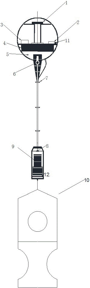
[0036] Such as figure 1 As shown, a ship-borne discarded radioactivity monitoring drifting buoy of the present invention includes a communication antenna 1, a satellite and GPS communication module 2, a control module 3, a battery 4, fillers 5, a steel cable connector 6, a cable clamp 7, Watertight connector 8, radiation detector 9, water sail 10, immersion sensor 11, CTD sensor 12.
[0037] The floating body of the present invention is in the form of a floating ball, which contains batteries 4 and fillers 5 to provide communication, measure energy and buoyancy for the buoy.
[0038] The lowest end of the present invention is the water sail 10, and then the radiation detector 9 and the...
PUM
 Abstract
Description
Claims
Application Information
 - R&D Engineer
- R&D Manager
- IP Professional
- Industry Leading Data Capabilities
- Powerful AI technology
- Patent DNA Extraction
Browse by: Latest US Patents, China's latest patents, Technical Efficacy Thesaurus, Application Domain, Technology Topic, Popular Technical Reports.
© 2024 PatSnap. All rights reserved.Legal|Privacy policy|Modern Slavery Act Transparency Statement|Sitemap|About US| Contact US: help@patsnap.com