Eureka AIR delivers breakthrough ideas for toughest innovation challenges, trusted by R&D personnel around the world.

Vehicle suspension and vehicle

A technology of vehicle suspension and oil cylinder, which is applied in the direction of suspension, elastic suspension, vehicle spring, etc., and can solve the problems that the ride comfort and driving safety cannot be effectively improved, the suspension stiffness and damping cannot be adjusted, and the performance of the vehicle is limited. , to achieve good anti-rolling effect, improve ride comfort, improve ride comfort and handling stability

Inactive Publication Date: 2017-02-22
张家口舒狮汽车科技有限公司
View PDF4 Cites 9 Cited by
  • Summary
  • Abstract
  • Description
  • Claims
  • Application Information

AI Technical Summary

Problems solved by technology

[0002] The stiffness and damping characteristics of the traditional car suspension cannot be changed after the design is completed, which greatly limits the further improvement of car performance. With the improvement of the performance and price reduction of various sensors and controllers of the car, the suspension stiffness and damping control is carried out through the controller And the practical application becomes possible. With the continuous improvement of people's requirements for the ride comfort of the car, the vibration isolation of the car suspension has attracted more and more attention.
The current automotive oil-pneumatic suspension is mainly a passive interconnected oil-pneumatic suspension. The anti-roll performance is improved by interconnecting the upper and lower oil cylinders of different wheel suspensions, and the multi-axis vehicle wheel load is evenly distributed. However, the suspension stiffness and damping cannot be adjusted. The ride comfort and driving safety of the vehicle cannot be effectively improved under different working conditions such as off-road, no-load, and full-load

Method used


Image

  • Vehicle suspension and vehicle
  • Vehicle suspension and vehicle

Examples


Embodiment Construction

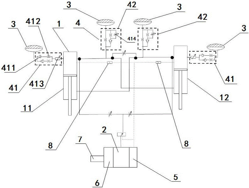
[0025] Such as figure 1 As shown, the present invention provides a vehicle suspension, including a power adjustment unit and an even number of oil cylinders. All the oil cylinders are divided into two groups, namely the left oil cylinder group and the right oil cylinder group, and the oil cylinders in the left oil cylinder group and the right oil cylinder group Each cylinder in the left cylinder group is connected with the corresponding cylinder in the right cylinder group, and each cylinder in the left cylinder group is connected with the corresponding cylinder in the right cylinder group; the cylinder is connected with the power adjustment unit connected.

[0026] A preferred embodiment, the number of oil cylinders 1 is two, which are respectively the first oil cylinder 11 and the second oil cylinder 12, the rodless chamber of the first oil cylinder 11 communicates with the rod chamber of the second oil cylinder 12, the first oil cylinder 11 The rod chamber of the oil cylin...


PUM


Abstract

The invention relates to a vehicle suspension. The vehicle suspension comprises a power regulating unit and an even number of oil cylinders, wherein the oil cylinders are divided into a left oil cylinder group and a right oil cylinder group, oil cylinders in the left oil cylinder group are in one-to-one correspondence to the oil cylinders in the right oil cylinder group, and the rod cavity of each oil cylinder in the left oil cylinder group is communicated with the rodless cavity of the corresponding oil cylinder in the right oil cylinder group; the oil cylinders are communicated with the power regulating unit. The vehicle suspension has the advantages that the rod cavities and the rodless cavities of the oil cylinders are connected, the motion tendency of the suspensions on two sides during vehicle during vehicle turning and roll, and a good anti-roll effect is achieved; the rodless cavities are parallelly connected with two energy accumulators, the rigidity of the suspension can be regulated according to driving conditions, and riding comfortableness and operation stability are increased effectively.

Description

technical field [0001] The invention belongs to the technical field of automobile suspensions, and in particular relates to a double air chamber variable stiffness anti-rolling oil-gas suspension. Background technique [0002] The stiffness and damping characteristics of the traditional car suspension cannot be changed after the design is completed, which greatly limits the further improvement of car performance. With the improvement of the performance and price reduction of various sensors and controllers of the car, the suspension stiffness and damping control is carried out through the controller And the practical application becomes possible. With the continuous improvement of people's requirements for the comfort performance of the car, the vibration isolation of the car suspension has attracted more and more attention. The current automotive oil-pneumatic suspension is mainly a passive interconnected oil-pneumatic suspension. The anti-roll performance is improved by in...

Claims


Application Information

Patent Timeline
IPC IPC(8): B60G17/04B60G17/056
CPCB60G17/0416B60G17/056B60G2202/414B60G2204/8304
Inventor 卢文丽
Owner 张家口舒狮汽车科技有限公司
Why Eureka
Eureka Blog
Learn More