Lateral support structure for eighteen-roll mill
A technology of side support and 18 rolls, which is applied in the field of stainless steel cold rolling, can solve the problems of insufficient lubrication, low reliability of the support device, small outer diameter of the mandrel, etc., double the lubrication efficiency, save the thickness of the inner ring, increase the Effect of Mandrel Diameter
- Summary
- Abstract
- Description
- Claims
- Application Information
AI Technical Summary
Problems solved by technology
Method used
Image

Examples
Embodiment 1
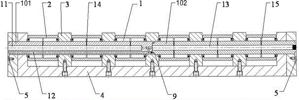
[0030] like figure 1 , Image 6 and Figure 7 As shown, the present embodiment provides a side support structure of an eighteen-high rolling mill, including a side support swing arm support 4, on which a side support roll 8 and a mandrel 1 are installed, and the mandrel 1 is a whole shaft formed by connecting multiple segmented mandrels through seams. The two ends of the mandrel 1 are equipped with a pressure plate 5, and the pressure plate 5 fixes the mandrel 1 to the side support swing arm support through bolts. 4; a plurality of evenly spaced backing bearings 2 are arranged in series on the mandrel 1, and partitions 3 are arranged between adjacent backing bearings 2, and the partitions 3 are fixed to the side support swing arm support 4 by bolts Above; the backing bearing 2 is composed of a bearing outer ring 201 and a bearing roller 202 , and the bearing roller 202 is in rolling contact with the mandrel 1 .
[0031] The working principle of the side support structure of...
Embodiment 2
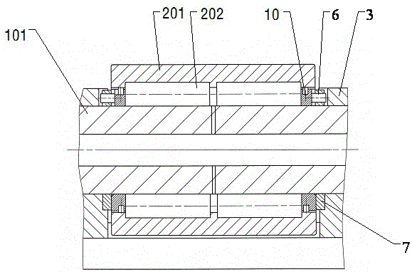
[0037] On the basis of Example 1, such as figure 1 and figure 2 As shown, the two ends of each of the backing bearings 2 are provided with a sealing retaining ring 10 sleeved on the mandrel 1, and the outer end of the sealing retaining ring 10 is provided with an adjustment ring 7 sleeved on the mandrel 1. The ring 7 is located between the sealing stop ring 10 and the partition 3 .
[0038] The backing bearing 2 in this embodiment adopts a structure without an inner ring, and the backing bearing rollers 202 roll directly on the mandrel 1 , and the diameter of the mandrel 1 can be increased, thereby improving the rigidity of the mandrel 1 .
[0039] But a problem that cannot be ignored is: the previous side support structure adopts the design of the backing bearing with the inner ring, and the width of the inner ring can be designed slightly wider than the distance between the two ends of the rolling element, as the axial clearance of the backing bearing; at the same time , ...
Embodiment 3
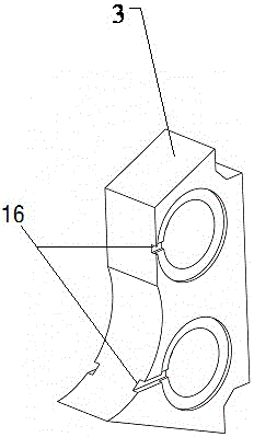
[0042] On the basis of Example 2, such as image 3 , Figure 4 and Figure 5As shown, the annulus of the sealing stop ring 10 and the separator 3 are provided with a groove 16 in the axial direction, and the annulus of the adjustment ring 7 is provided with a through hole in the axial direction, and the pin shaft 6 passes through the through hole. , and both ends are stuck in the groove 16 of the sealing stop ring 10 and the separator 3 respectively.
[0043] Regarding the rotation of the backing bearing 2 mentioned in Embodiment 2, the seal stop ring 10 and the adjustment ring 7 will follow the rotation of the bearing when there is a certain gap in the axial direction, that is, the relative rotation of the adjustment ring 7 and the seal stop ring 10 questions such as image 3 , Figure 4 and Figure 5 As shown, a through hole is designed on the adjusting ring 7, the pin shaft 6 passes through the through hole and both ends protrude from the end face of the adjusting ring...
PUM
 Abstract
Description
Claims
Application Information
 - Generate Ideas
- Intellectual Property
- Life Sciences
- Materials
- Tech Scout
- Unparalleled Data Quality
- Higher Quality Content
- 60% Fewer Hallucinations
Browse by: Latest US Patents, China's latest patents, Technical Efficacy Thesaurus, Application Domain, Technology Topic, Popular Technical Reports.
© 2025 PatSnap. All rights reserved.Legal|Privacy policy|Modern Slavery Act Transparency Statement|Sitemap|About US| Contact US: help@patsnap.com