
Visual laryngoscope

A technology of laryngoscope and larynx, applied in the field of video laryngoscope, can solve the problems of difference in opening degree series, complicated assembly and replacement process, and inability to use multiple instruments together, so as to increase data interface and enhance tightness. Solid, to meet the effect of efficient and stable assembly

Inactive Publication Date: 2017-02-22
HANGZHOU CHUANGHUI MEDICAL ELECTRONICS EQUIP CO LTD
View PDF18 Cites 7 Cited by
  • Summary
  • Abstract
  • Description
  • Claims
  • Application Information

AI Technical Summary

Problems solved by technology

[0003] 1. The existing insertion blades, such as Miller, Micintosh or Wisconsin blades, are usually L-shaped blades. When the endotracheal tube is inserted, due to the curvature of the blades, there is resistance during insertion, and the insertion process is relatively difficult.
[0004] 2. Conventional blades are basically flat blades, but according to the characteristics of the throat, curved blades are required to enter the throat through the oropharynx
[0005] 3. The shooting component in the conventional disposable blade can be reused, and it is installed in the shooting cavity in the blade, and the assembly and replacement process is relatively complicated
[0006] 4. Due to the difference in the mouth shape of the patient and the difference in the degree of opening, it is necessary to use blades of different specifications, and even some difficult respiratory tracts will directly use devices such as visual tracheal intubation or visual suction tube. The existing video laryngoscope cannot Compatible with a variety of devices
[0007] 5. The assembly of the main body and blades of the video laryngoscope cannot take into account firmness and convenience, and the stability and effectiveness of the connection structure of the electrical signal are also poor

Method used


Image

  • Visual laryngoscope
  • Visual laryngoscope
  • Visual laryngoscope

Examples


Embodiment Construction

[0047] like Figure 2 to Figure 4 As shown, the present invention provides a video laryngoscope, which is used to elevate the tissue near the epiglottis of the patient and collect images of the patient's larynx. The video laryngoscope of the present invention includes a main body 1 and a disposable blade 2, the main body 1 It includes a display screen 11 and a handle 12.

[0048] like Figure 5 and Image 6 As shown, the disposable blade 2 has a sealed shooting chamber and a tube guide 25, the side of the shooting chamber has a shooting chamber cover plate 21, and a shooting assembly is installed in the shooting chamber, and the shooting assembly is composed of a camera assembly 231, a data line 232 and a flexible circuit board 233, the end of the shooting cavity has a shooting window, the shooting window is provided with a camera bracket 22, the camera assembly 231 is fixed on the camera bracket 22, the shooting There is a circuit board installation groove 24 at the end of...


PUM

PropertyMeasurementUnit
Radiusaaaaaaaaaa

Abstract

The invention discloses a visual laryngoscope used for lifting up patient tissues nearby the epiglottis and collecting patient throat images; the visual laryngoscope comprises a body and a disposable blade; the body comprises a display and a handle; the disposable blade comprises a sealed camera cavity and a tube guide member; the side portion of the camera cavity is provided with a cover plate; a camera assembly is arranged in the camera cavity, and comprises a camera head assembly, a data line and a flexible circuit board; the end portion of the camera cavity is provided with a shooting window having a camera head support; the camera head assembly is fixed on the camera head support; the tail of the camera cavity is provided with a circuit board mount slot; the flexible circuit board penetrates the circuit board mount slot and is folded and fixed. The visual laryngoscope complies with human body throat characteristic curvature, a trachea conduit can be conveniently inserted, and the camera assembly blade can be assembled with high efficiency; in addition, the body and blade fixing mode can be improved, thus enhancing connecting portion tightness and electric signal connection stabilization and convenience characteristics.

Description

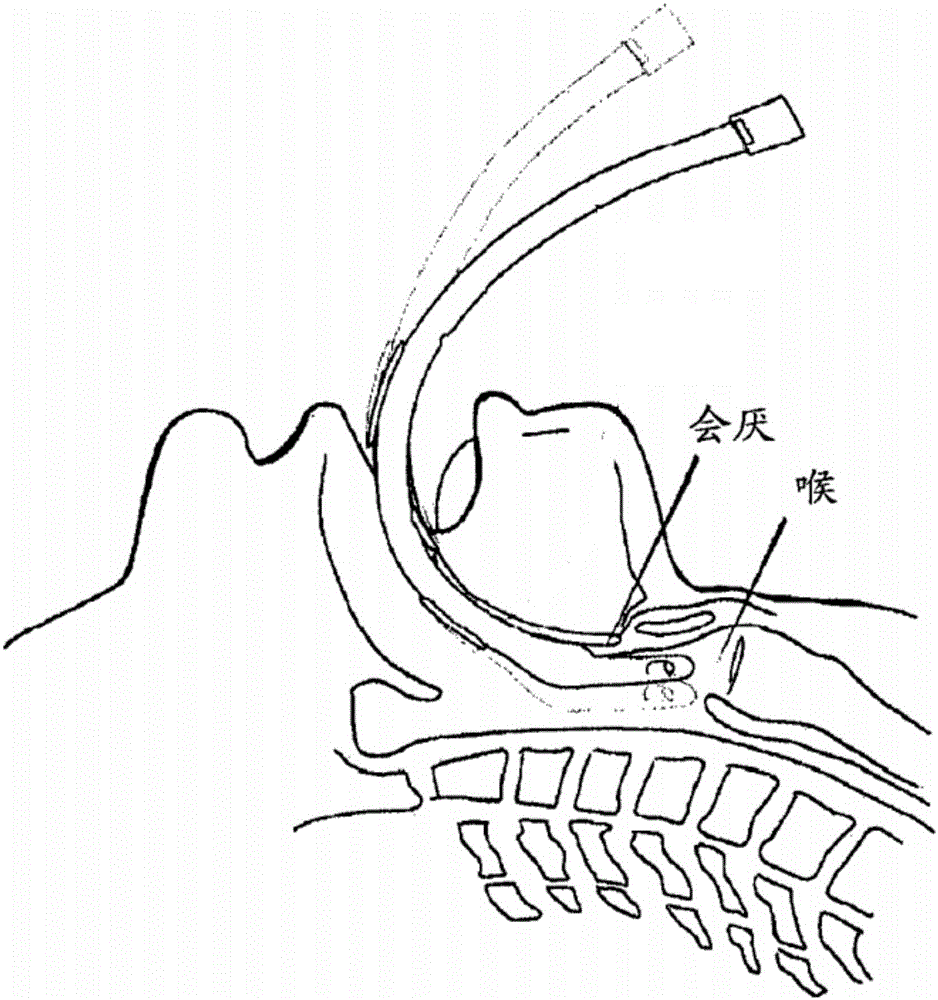
technical field [0001] The invention relates to a medical device for the larynx, in particular to a video laryngoscope. Background technique [0002] like figure 1 As shown, the laryngoscope is a commonly used medical device in oral, laryngeal and tracheal medical procedures. It is used to elevate the tissue near the patient's epiglottis to collect images of the patient's larynx. Tracheal intubation using a laryngoscope is a commonly used technique in first aid and anesthesia work. The traditional laryngoscope is an optical laryngoscope. The doctor needs to rely on the blade inserted into the patient's larynx to observe the condition of the larynx. The patient suffers a lot. Some known video laryngoscopes have improved this, and achieved good results by placing a micro-camera in the blade to observe the larynx, but there are still some problems to be optimized as follows: [0003] 1. The existing insertion blades, such as Miller, Micintosh or Wisconsin blades, are usually ...

Claims


Application Information

Patent Timeline
IPC IPC(8): A61B1/267A61B1/04A61B1/06A61B1/018
CPCA61B1/267A61B1/00071A61B1/018A61B1/04A61B1/0684
Inventor 刘华陆海同张申钱大宏杜铭
Owner HANGZHOU CHUANGHUI MEDICAL ELECTRONICS EQUIP CO LTD
Learn More