
Electric working machine

A working machine and electric technology, applied in the direction of AC motor control, motor speed or torque control, cleaning machinery, etc., to achieve the effect of ensuring insulation distance

Active Publication Date: 2020-07-17
MAKITA CORP
View PDF4 Cites 0 Cited by
  • Summary
  • Abstract
  • Description
  • Claims
  • Application Information

AI Technical Summary

Problems solved by technology

In general, AC / DC converters have insulation transformers inside, so dust collectors equipped with AC / DC converters have become larger

Method used


Image

  • Electric working machine
  • Electric working machine
  • Electric working machine

Examples


Embodiment approach 1

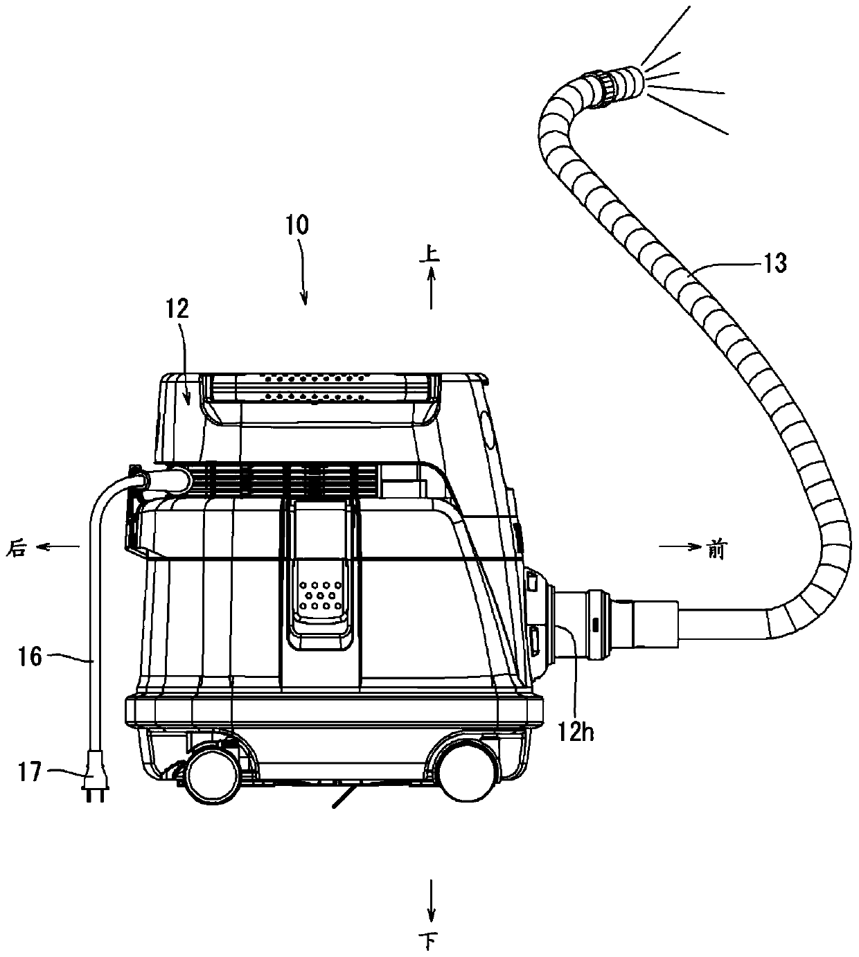
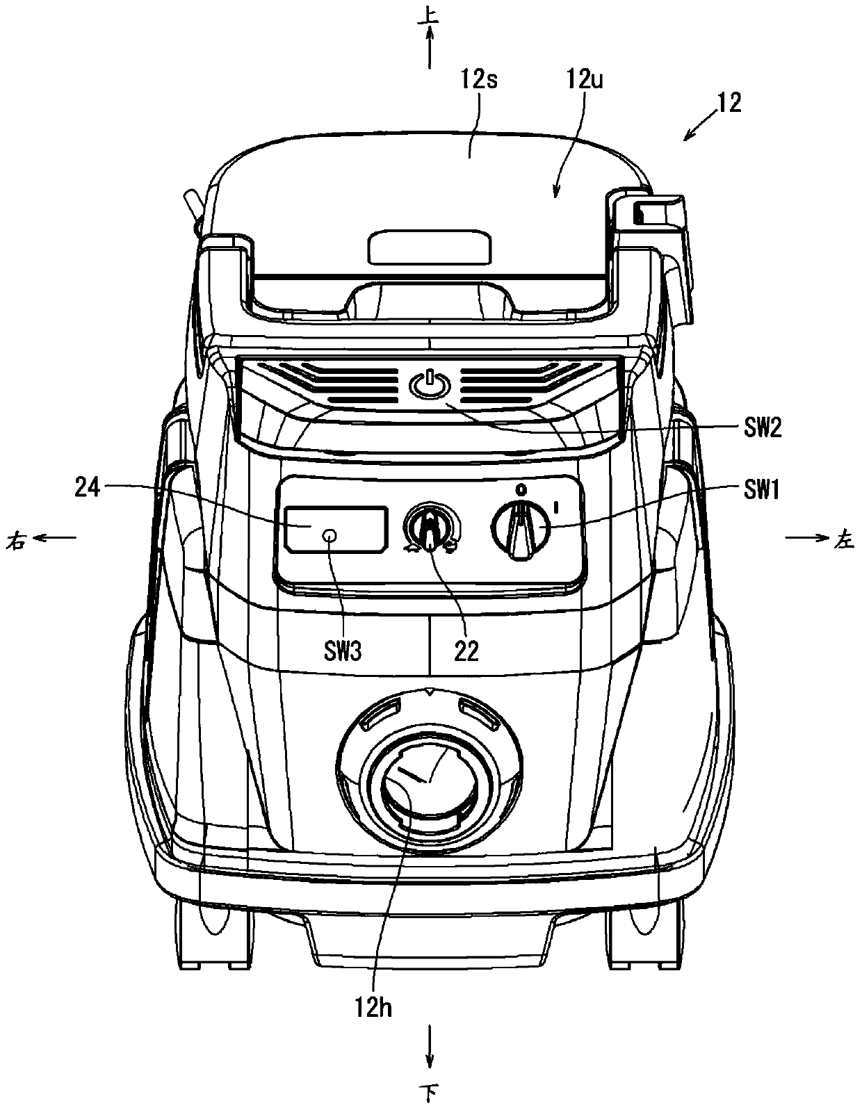
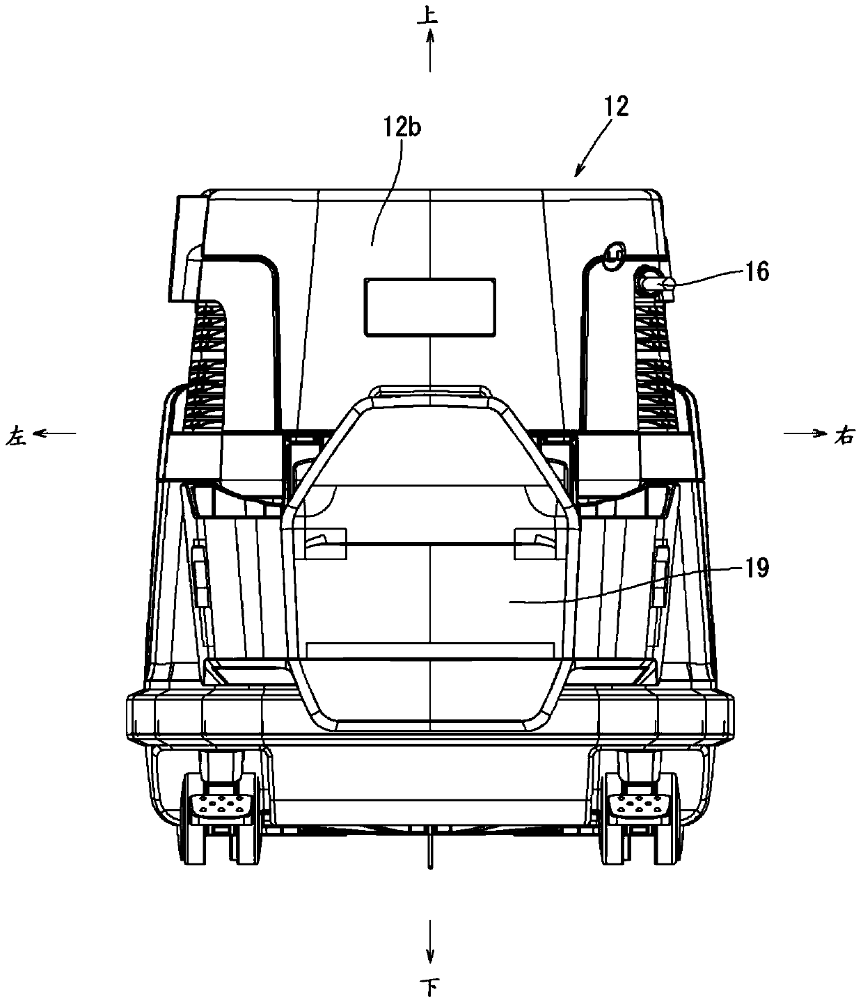
[0033] Below, according to Figure 1 to Figure 10 , the electric working machine according to Embodiment 1 of the present invention will be described. The electric working machine according to the present embodiment is a dust collector 10 that sucks machining chips and the like generated when an object is machined using a tool. Here, the front, rear, left, right, and up and down shown in the drawings correspond to the front, back, left, and right, and up and down of the dust collector 10 .

[0034]

[0035] Such as figure 1 As shown, the dust collector 10 is composed of a dust collector main body 12 and a suction hose 13 connected to a dust collection port 12h of the dust collector main body 12 . The dust collector main body 12 is constituted as a motor 14 (refer to Image 6 The circuit diagram of ) rotates a fan (not shown in the figure) to generate an air flow, whereby outside air can be sucked from the dust collection port 12h via the suction hose 13 . And the dust co...


PUM


Abstract

An object of the present invention is to compactly manufacture an electric working machine that can be driven by both AC and DC power sources. The present invention relates to an electric working machine that can be connected to an AC power source and a DC power source, comprising: a motor (14) configured to be driven by AC power or DC power; and an AC circuit (30) for driving the motor. AC power is supplied to the motor (14); a motor-driving DC circuit (40), which supplies DC power to the motor (14); a switching unit (RL1 to RL12), which switches the motor-driving AC circuit in a state of electrical insulation (30) and the DC circuit (40) for motor driving; Take control.

Description

technical field [0001] The present invention relates to an electric working machine configured to be connectable to an AC power source and a DC power source. Background technique [0002] Patent Document 1 describes an electric working machine related to this. The above-mentioned electric working machine is an AC / DC type dust collector, and includes a DC motor as a drive source. In addition, the AC power supplied from the outlet is converted into DC power by an AC / DC converter, and then supplied to the DC motor. Moreover, it is also comprised so that the DC electric power supplied by the battery can be supplied to the said DC motor via a DC / DC converter. [0003] Patent Document 1: Japanese Patent Laid-Open No. 2004-160235 [0004] The said AC / DC type dust collector is equipped with the AC / DC converter etc. which convert AC power into DC power. Generally, since an AC / DC converter includes an insulation transformer inside, the size of the dust collector equipped with the ...

Claims


Application Information

Patent Timeline
Patent Type & Authority Patents(China)
IPC IPC(8): A47L5/14A47L5/24A47L5/36A47L7/00A47L9/00A47L9/22A47L9/24A47L9/26A47L9/28A47L11/40
CPCA47L5/14A47L5/24A47L5/36A47L7/0028A47L7/0038A47L7/0042A47L9/0009A47L9/0027A47L9/0045A47L9/22A47L9/242A47L9/26A47L9/2878A47L9/2889A47L11/4019H02J2207/40H02P4/00H02P25/14A47L5/12H02K11/33
Inventor 草川卓也林克名
Owner MAKITA CORP
Learn More