Component mounting machine

A technology for installing machines and components, applied in the direction of electrical components, electrical components, manipulators, etc., can solve the problems of reduced productivity, increased number of types, increased frequency of replacing chuck devices, etc., and achieve the effect of improving productivity

Active Publication Date: 2017-02-15
FUJI KK
View PDF5 Cites 9 Cited by
  • Summary
  • Abstract
  • Description
  • Claims
  • Application Information

AI Technical Summary

Problems solved by technology

Therefore, there is not only the disadvantage that the frequency of replacement of the chuck device during production increases and the productivity decreases, but also the disadvantage that the number of types of chuck devices to be prepared increases and the cost of the device increases.

Method used


Image

  • Component mounting machine
  • Component mounting machine
  • Component mounting machine

Examples


Embodiment Construction

[0037] Hereinafter, an example which actualizes the embodiment for implementing this invention is demonstrated.

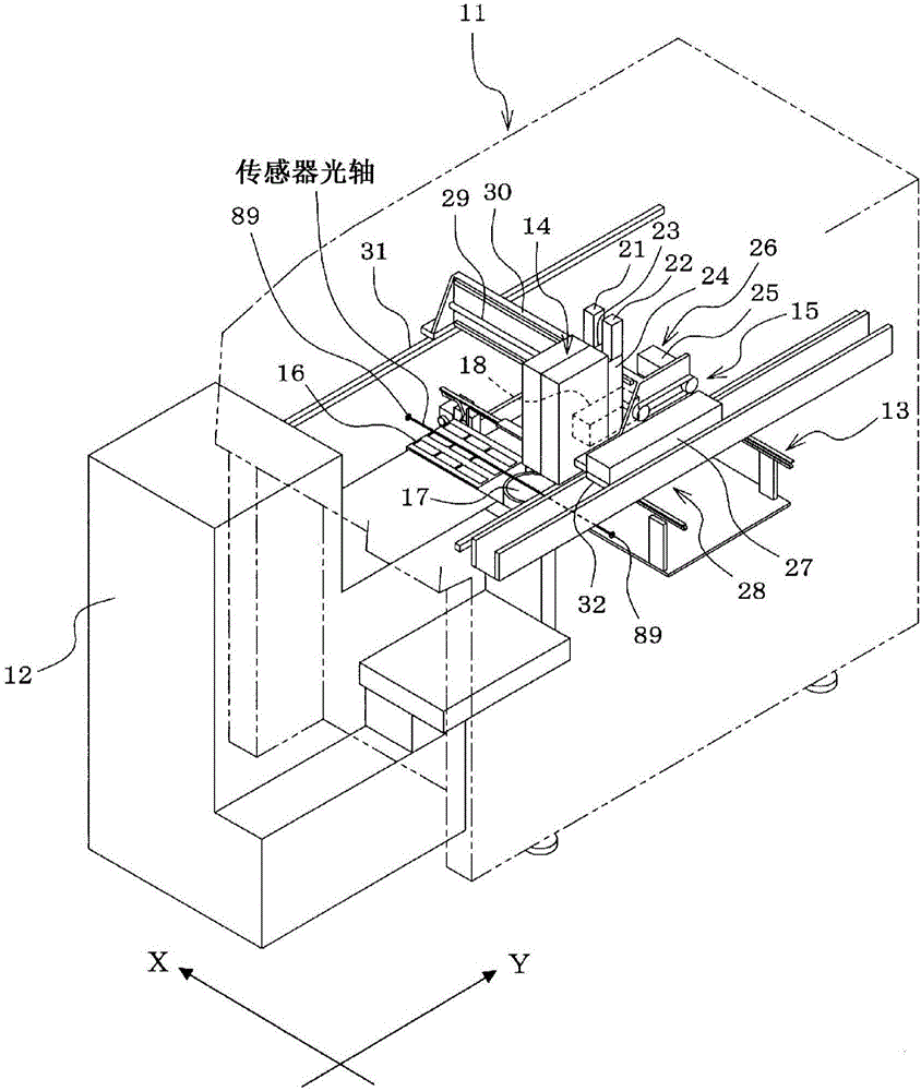
[0038] First, based on figure 1 The structure of the component mounting machine 11 will be described.

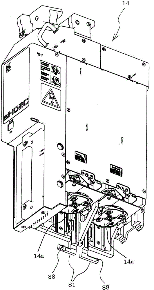
[0039] A component supply device 12 for supplying components is detachably provided on the component mounting machine 11 . The component supply device 12 provided in the component mounting machine 11 can be any one of a tray feeder, a tape feeder, a bulk feeder, a bar feeder, etc. Of course, it is also possible to mix and load a variety of feeder. The component mounting machine 11 is provided with a conveyor 13 for conveying circuit boards (not shown), a mounting head 14 for mounting components supplied from the component supply device 12 on the circuit board, and the mounting head 14 is arranged along the XY axis directions (left and right). The XY-axis moving mechanism 15 that moves in the front-rear direction), the tool station 16 on which the tool for repl...


PUM


Abstract

A chuck device (40) is provided with: a plurality of types of chuck jaws (51) for holding components therebetween; a chuck-jaw selecting mechanism (58) which selects, from among the plurality of types of chuck jaws (51), in accordance with the type of the component to be held therebetween, the chuck jaws (51) to be used; and a drive mechanism (65) which causes the chuck jaws (51) selected by the chuck-jaw selecting mechanism (58) to hold the component therebetween. The chuck-jaw selecting mechanism (58) rotates a cylindrical cam (50) while rotation of a cylindrical guide member (53) provided to the outer peripheral side of the cylindrical cam (50) is in a locked state, to respectively and independently move each of the chuck jaws (51) vertically, and select the chuck jaws (51) to be used. A mounting head (14) is provided with: a rotation-locking member (81) for locking the rotation of the cylindrical guide member (53) during selection of the chuck jaws (51) to be used; and a cam follower (87) for moving the rotation-locking member (81).

Description

technical field [0001] The present invention relates to a component mounting machine that holds a chuck device for clamping and mounting components on a circuit board or the like in a mounting head. Background technique [0002] When components are mounted on circuit boards, etc. by a component mounter, large components or special-shaped components that are difficult to pick up by suction nozzles are gripped and transported by the chuck claws of the chuck device. Usually, in most cases, the chuck device clamps the component from both sides of the component by a pair of (two) chuck jaws, but there is also the In this way, two pairs (four) of chuck jaws are arranged at 90° intervals, and the two pairs of chuck jaws perform clamping action simultaneously to clamp the component from four directions of the component. [0003] Patent Document 1: Japanese Patent Application Publication No. 6-24882 Contents of the invention [0004] Since any of the above-mentioned chuck devices...

Claims


Application Information

Patent Timeline
Patent Type & Authority Applications(China)
IPC IPC(8): H05K13/04B25J15/04
CPCB25J15/04H05K13/0404H05K13/041H05K13/0408Y10T29/53174H05K3/303
Inventor 山室淳市
Owner FUJI KK
Why Eureka
Try Eureka