A kind of antenna equipment and terminal

An antenna device and antenna technology, applied in the direction of antenna, antenna coupling, antenna components, etc., can solve the problems affecting the accuracy of the antenna device's emission direction and affecting the antenna device's direction diagram, etc.

Active Publication Date: 2021-01-05
HUAWEI TECH CO LTD
View PDF7 Cites 1 Cited by
  • Summary
  • Abstract
  • Description
  • Claims
  • Application Information

AI Technical Summary

Problems solved by technology

[0003] For example, if the antenna is set at the lower right corner of the board, but due to the guiding effect of the "ground" current on the two board edges (especially the longer board edge) close to the area where the antenna is located on the board, so that The radiation pattern of the antenna equipment produces side lobes, and the main lobe and side lobe of the radiation diagram shift to the upper left, which affects the radiation pattern of the antenna equipment and affects the accuracy of the radiation direction of the antenna equipment

Method used


Image

  • A kind of antenna equipment and terminal
  • A kind of antenna equipment and terminal
  • A kind of antenna equipment and terminal

Examples


Embodiment 1

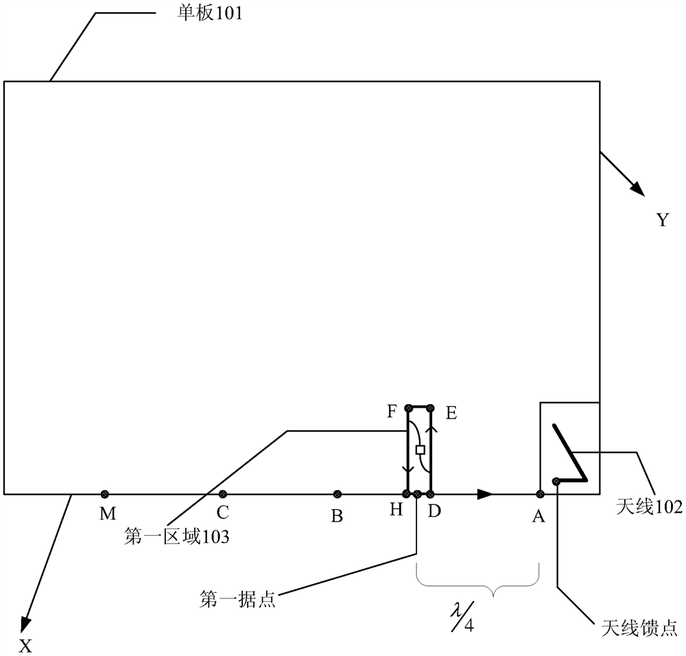
[0027] An embodiment of the present invention provides an antenna device, such as image 3 As shown, the antenna includes: a single board 101 , an antenna 102 disposed on the single board, and a first region 103 disposed on the single board 101 without a metal layer. It can be understood that the area where the antenna 102 is located is a clear area, and the projection area of ​​the antenna 102 on the single board 101 (the area surrounded by the solid line in the lower right corner) is not covered with a metal layer.

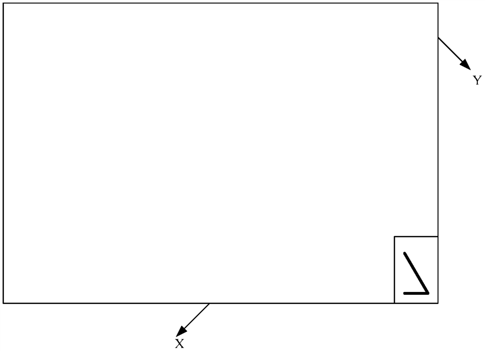
[0028] Wherein, the first edge X of the single board 101 is the longer single board edge among the two single board edges close to the antenna. On the first edge X, the point with a distance of λ / 4 from the first maximum current point A on the first edge X is the first stronghold, and the first maximum current point A is the The maximum current point on the first edge that is closest to the antenna feed point. The λ is the working wavelength of the antenna 102...

Embodiment 2

[0035] An embodiment of the present invention provides an antenna device, such as Figure 5 As shown, the antenna device includes the single board 101 described in the above embodiment, the antenna 102 disposed on the single board, and the first region 103 provided on the single board without a metal layer, It also includes a second region 104 on the veneer that is not covered with a metal layer.

[0036] Wherein, the first edge X of the veneer 101 is the longer veneer edge among the two veneer edges close to the antenna; A point with a distance of λ / 4 between the maximum current points is the first base point, and the first maximum current point A is the maximum current point on the first edge closest to the antenna feeding point. The λ is the working wavelength of the antenna 102 . It should be noted that the wavelength of the electromagnetic wave corresponds to a frequency, such as 2.4GHZ, and the center frequency is 2.45GHZ. Since λ*f=C, where f is the frequency, C is t...


PUM


Abstract

Embodiments of the present invention provide an antenna device and a terminal, which relate to the communication field and can restrain the direction of "ground" current on the edge of the single board where the antenna is located. Including: the antenna, the single board provided with the antenna, and also: the first area provided on the single board without the metal layer, wherein the first edge of the single board is the longer of the two single board edges close to the antenna on the edge of the veneer; on the first edge, the point with a distance of λ/4 from the first maximum current point on the first edge is the first stronghold; wherein, the first maximum current point is the distance on the first edge from The current maximum point nearest to the feeding point of the antenna, λ is the operating wavelength of the antenna; the first area without the metal layer includes the first stronghold, and the maximum distance from the edge of the first area to the first edge of the veneer is The distance is λ/4.

Description

technical field [0001] The present invention relates to the communication field, in particular to an antenna device and a terminal. Background technique [0002] The performance of the existing antenna device (the antenna is arranged on the single board) is ordinary, and its pattern is easily affected by the guiding effect of the "ground" current on the edge of the single board, especially the edge of the single board near the area where the antenna is located. Wherein, the longer the edge of the veneer is, the greater the guiding effect of the "ground" current on the edge is. [0003] For example, if the antenna is set at the lower right corner of the board, but due to the guiding effect of the "ground" current on the two board edges (especially the longer board edge) close to the area where the antenna is located on the board, so that The directional pattern of the antenna device produces side lobes, and the main lobe and side lobes of the directional pattern shift to the...

Claims


Application Information

Patent Timeline
Patent Type & Authority Patents(China)
IPC IPC(8): H01Q1/48H01Q1/52
CPCH01Q1/243H01Q1/38H01Q1/48H01Q1/52H01Q3/00
Inventor 毛政言王克猛朱德进高晓萍龚贻文吴松王威
Owner HUAWEI TECH CO LTD
Why Eureka
Try Eureka