Device and method for converting heat energy

A technology of thermal energy and thermal energy conversion, applied in the field of thermal energy devices, can solve problems such as unsatisfactory results

Active Publication Date: 2019-04-30
ECOP TECH
View PDF7 Cites 0 Cited by
  • Summary
  • Abstract
  • Description
  • Claims
  • Application Information

AI Technical Summary

Problems solved by technology

[0007] However, it has been shown in numerous tests that the arrangements of the impellers known from the prior art do not provide satisfactory results in such devices in which the inlet and outlet structures of the impeller are arranged in rotation in the rotor housing.

Method used


Image

  • Device and method for converting heat energy
  • Device and method for converting heat energy
  • Device and method for converting heat energy

Examples


Embodiment Construction

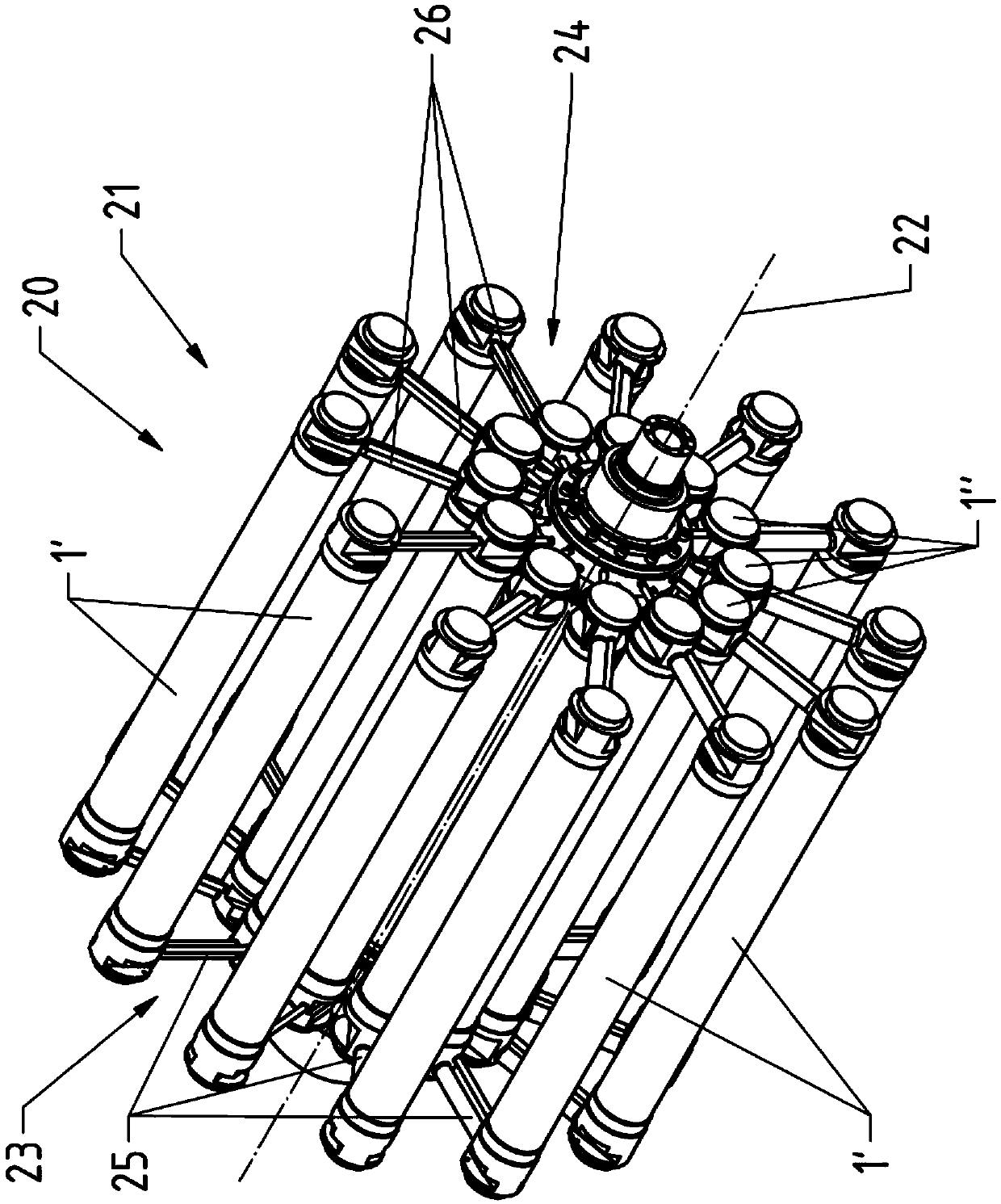
[0045] figure 1A device 20 for converting thermal energy by means of mechanical energy and reversing the process is shown, which in the embodiment shown acts as a heat pump. The device 20 contains a rotor 21 which can be rotated about an axis of rotation 22 by means of a motor (not shown). The rotor 21 has a compression unit 23 and a pressure reduction unit 24 which have flow channels for the working medium. While flowing through the rotor 21, the working medium, for example natural gas, passes through a closed cycle process with the working steps: a) compression of the working medium, b) between the working medium and the heat exchange medium in the external heat exchanger 1' between, c) depressurization of the working medium and d) heat exchange between the working medium and the heat exchange medium in the internal heat exchanger 1". For this purpose, the compression unit 23 has a substantially radially extending A compression channel 25 in which the working medium flows ...


PUM


Abstract

A device and a method for converting low temperature thermal energy into high temperature thermal energy using mechanical energy with a rotor for a working medium passing through a closed cycle. The rotor has a compressor unit with compression channels and an expansion unit with expansion channels, and has heat exchangers for exchanging heat between the working medium and a heat exchange medium. The device has an impeller which can be rotated relative to the rotor. The impeller is arranged between supply channels which conduct the flow of the working medium in the heat pump and at least one rotor discharge channel which discharges the flow of the working medium in the heat pump. The supply channels have outlet sections which extend up to a point directly upstream of an inlet opening of the impeller such that flows of the working medium are conducted out of the supply channels.

Description

technical field [0001] The present invention relates to a device for converting lower temperature thermal energy into higher temperature thermal energy and converting higher temperature thermal energy into lower temperature thermal energy by utilizing mechanical energy, which has a device for passing through A rotor of the working medium in a closed cycle process and an impeller rotatable relative to the rotor, wherein the rotor has a compression unit with a plurality of compression channels and a pressure reduction unit with a plurality of pressure reduction channels, the flow of the working medium can be increased in order to increase the pressure Leading substantially radially outwards with respect to the axis of rotation into the compression channel, the flow of the working medium can be directed essentially radially inwards with reference to the axis of rotation into the pressure relief channel for reducing the pressure, wherein the rotor also has an A heat exchanger for ...

Claims


Application Information

Patent Timeline
Patent Type & Authority Patents(China)
IPC IPC(8): F25B3/00
CPCF25B3/00F25B9/00
Inventor A.伯恩哈德
Owner ECOP TECH
Why Eureka
Try Eureka