Internal and external rotation generator

A generator, internal and external rotation technology, applied in the direction of electrical components, electromechanical devices, electric components, etc., can solve the problems of inability to generate electricity, low mileage of electric vehicles, and short service life of batteries, so as to improve battery life, improve use efficiency, Energy Saving Effect

Inactive Publication Date: 2017-02-15
李德春
View PDF4 Cites 0 Cited by
  • Summary
  • Abstract
  • Description
  • Claims
  • Application Information

AI Technical Summary

Problems solved by technology

[0003] At present, the power supply of domestic electric vehicles mainly depends on the power supply mode of rechargeable batteries or rechargeable batteries and power generation. ;The structure of a general power generator is that a rotor rotates around a stator to cut the magnetic induction line to generate electricity. The generator rotor needs to reach at least 1500r / min to generate electricity. The speed requirement of the electric vehicle is relatively high, so the general power generator has low In the case of high speed, there are disadvantages of inability to generate electricity or insufficient electricity generation, and there are also problems such as poor supporting facilities for electric vehicles, unsatisfactory battery life, and safety hazards such as long-term charging and cumbersome operations.

Method used


Image

  • Internal and external rotation generator

Examples


Embodiment Construction

[0021] In order to further understand the present invention, the preferred embodiments of the present invention are described below in conjunction with examples, but it should be understood that these descriptions are only to further illustrate the features and advantages of the present invention, rather than limiting the claims of the present invention.

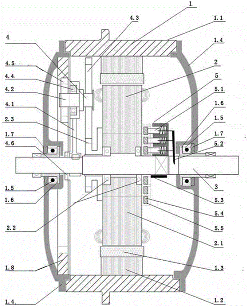
[0022] The present invention includes an external rotation device 1, an internal rotation device 2, a rotor shaft 3, a linkage device 4 and a conductive device 5 with permanent magnets 1.3, wherein the external rotation device 1 is installed on the rotor shaft 3; The device 2 is installed on the rotor shaft 3 and located inside the external rotation device 1; the linkage device 4 is fixedly installed on the rotor shaft 3 and located on one side of the internal rotation device 2; the conductive device 5 It is fixedly installed on the rotor shaft 3 and located on the other side of the inner turning device 2; the outer turning d...


PUM


Abstract

The invention belongs to the generator technology field and especially relates to an internal and external rotation generator applied to various kinds of electric vehicles and wind power generation equipment. The internal and external rotation generator comprises an outer rotation device 1 possessing a permanent magnet 1.3, an inner rotation device 2, a rotor shaft 3, a linkage apparatus 4 and a conductive apparatus 5. The outer rotation device 1 is installed on the rotor shaft 3. The inner rotation device 2 is installed at a position on the rotor shaft 3, wherein the position is located in an internal portion of the outer rotation device 1. The linkage apparatus 4 is fixedly installed at a position on the rotor shaft 3, wherein the position is located at one side of the inner rotation device 2. The conductive apparatus 5 is fixedly installed at a position on the rotor shaft 3, wherein the position is located at the other side of the inner rotation device 2. The outer rotation device 1 drives the inner rotation device 2 to carry out positive and negative direction rotation motion through the linkage apparatus 4. The internal and external rotation generator possesses advantages that energy saving and emission reduction are achieved; power generation is realized through a low rotating speed; a generating capacity is large; a storage battery service life is prolonged; and a cell endurance capability is increased and so on.

Description

technical field [0001] The invention belongs to the technical field of generators, and in particular relates to an internal and external rotation generator applied to various electric vehicles and wind power generation equipment. Background technique [0002] The electric vehicle industry has rapidly grown into a key industry related to the people's livelihood due to the advantages of electric vehicles such as low-carbon environmental protection, lightness and flexibility, and high cost performance (only about 7 cents per kilometer). According to the "2014-2018 China Electric Vehicle Industry Market Demand Forecast and Investment Planning Analysis Report" released by Qianzhan Industry Research Institute, electric vehicles, as an energy-saving and cheap travel tool, occupy an important position in solving China's future transportation problems. In 5 years, the number of electric bicycles in China will exceed 300 million. [0003] At present, the power supply of domestic elec...

Claims


Application Information

Patent Timeline
Patent Type & Authority Applications(China)
IPC IPC(8): H02K16/02H02K7/116
CPCH02K7/116H02K16/02
Inventor 李德春
Owner 李德春
Why Eureka
Try Eureka