
Object Movement Pattern Recognition Method Based on Multi-Channel Continuous Wave Doppler Radar

A technology for object movement and pattern recognition, applied in radio wave measurement systems, instruments, etc., can solve problems such as inability to realize large dynamic range movement, few movement pattern recognition, etc., achieve low cost, strong anti-interference ability, and recognition accuracy high effect

Active Publication Date: 2018-11-13
ZHEJIANG UNIV
View PDF6 Cites 0 Cited by
  • Summary
  • Abstract
  • Description
  • Claims
  • Application Information

AI Technical Summary

Problems solved by technology

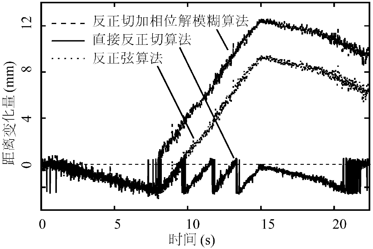
Previously, the baseband demodulation algorithm used generally used the small-angle approximation principle or arctangent operation, which could not realize the measurement of large dynamic range motion in low sampling rate scenarios
Also, previous CW Doppler radar or radar sensors were mostly used to measure one-dimensional motion and were rarely used for motion pattern recognition applications

Method used


Image

  • Object Movement Pattern Recognition Method Based on Multi-Channel Continuous Wave Doppler Radar
  • Object Movement Pattern Recognition Method Based on Multi-Channel Continuous Wave Doppler Radar
  • Object Movement Pattern Recognition Method Based on Multi-Channel Continuous Wave Doppler Radar

Examples


Embodiment approach

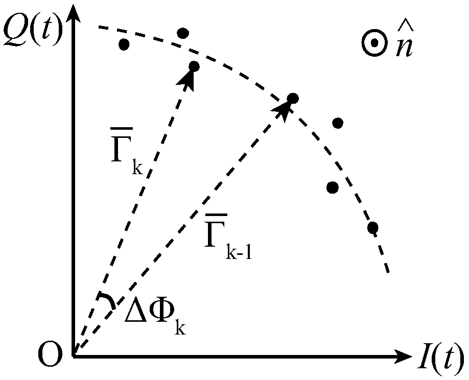
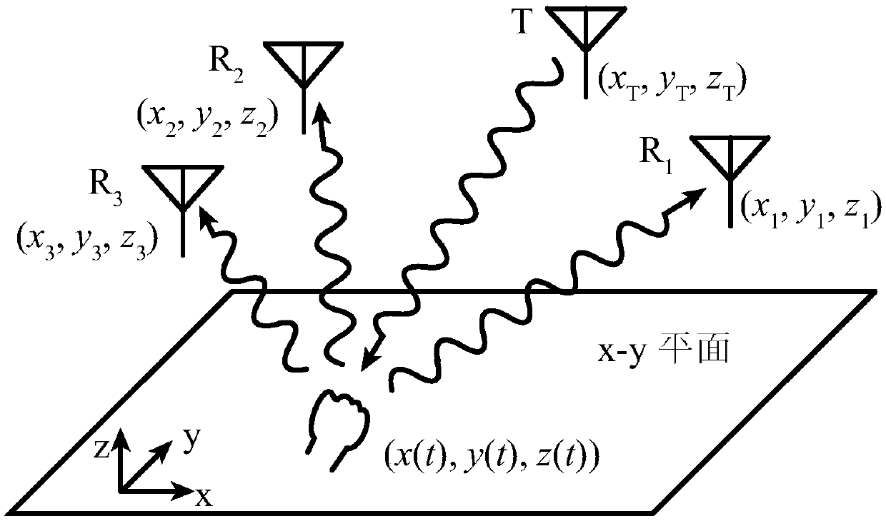
[0028] The RF front-end emits electromagnetic waves through a transmitting antenna, irradiating the surface of the moving object to be measured, and the reflected signal is received by two receiving antennas and down-converted to the baseband. For any quadrature down-conversion receiver, after the quadrature I and Q signals output by it are sampled, the distance change information x(t) of the object to be measured can be expressed as:

[0029]

[0030]

[0031] where DC I (t) and DC Q (t) is the DC offset, A I (t) and A Q (t) is the amplitude of the I and Q signals (the two can be considered equal during quadrature demodulation), λ, θ 0 Respectively represent the wavelength of the electromagnetic wave, the residual phase noise of the transceiver (which can be considered equal to 0 in correlation demodulation) and the additional phase difference of the transceiver signal. So x(t) can be obtained by

[0032]

[0033] Since the inverse trigonometric function has a...


PUM


Abstract

The present invention provides an object motion identification method based on a multi-channel continuous-wave Doppler radar. One antenna is employed to emit electromagnetic wave to irradiate the surface of a motion object to be measured, the reflected signals are received by 2-3 receiving antennas and are subjected to down conversion to a base band, the arcsine algorithm is employed to demodulate the phase information without the phase ambiguity limitation, the distance changing information between each receiving antenna and the motion object is obtained, the track formula is employed to obtain the object's motion track, and the mode identification is performed on the basis of the motion track. The object motion identification method based on the multi-channel continuous-wave Doppler radar can avoid the phase ambiguity problem of the arc tangent class function, is applied to the work condition with high the sampling rate and work condition with the low sampling rate and keeps the accuracy in the condition with the low sampling rate. The mode identification is realized on the basis of location and tracking of the object to be measured. The identification accuracy is high, the anti-interference capability is high, the configuration is simple, and the cost is low, the most of the demodulated motions are the linear relation with no need for the complex data processing process, and the hardware resource is saved.

Description

technical field [0001] The invention relates to a non-contact method for object movement pattern recognition, in particular to an object movement pattern recognition method based on multi-channel continuous wave Doppler radar. Background technique [0002] Motion detection using continuous wave Doppler radar or radar sensor technology has made great progress in recent years. The continuous wave radar sensor works at a single frequency, and has outstanding advantages such as simple structure, low cost, good integration, and strong anti-interference ability. Previously, the baseband demodulation algorithm used generally used the small-angle approximation principle or arctangent operation, which could not realize the measurement of large dynamic range motion in low sampling rate scenarios. Additionally, previous continuous wave Doppler radar or radar sensors have mostly been used to measure one-dimensional motion and have rarely been used for motion pattern recognition applica...

Claims


Application Information

Patent Timeline
Patent Type & Authority Patents(China)
IPC IPC(8): G01S7/41
CPCG01S7/415
Inventor 范腾龙冉立新
Owner ZHEJIANG UNIV
Learn More