
Web beam structure anti-destabilization clamper under fatigue shear load effect

A technology of shear load and beam structure, applied in the direction of measuring devices, instruments, scientific instruments, etc., can solve problems such as lateral instability

Inactive Publication Date: 2017-02-15
HARBIN
View PDF8 Cites 4 Cited by
  • Summary
  • Abstract
  • Description
  • Claims
  • Application Information

AI Technical Summary

Problems solved by technology

On the one hand, under the action of compressive load, the beam flange may cause lateral instability. On the other hand, considering that the position of the loaded load may have a slight deviation from the center of the section of the test piece, additional torque will be generated on the test piece, resulting in torsional deformation.

Method used


Image

  • Web beam structure anti-destabilization clamper under fatigue shear load effect
  • Web beam structure anti-destabilization clamper under fatigue shear load effect

Examples


Embodiment Construction

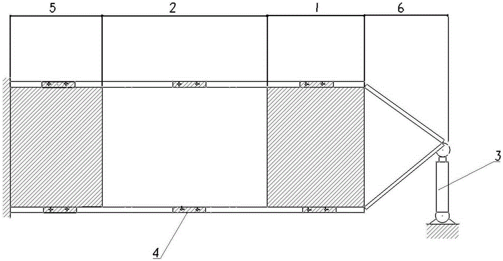
[0015] Before the test, select the largest unit fatigue load for analysis, determine the deformation of the test piece, and then determine the size of the clamping plate, so that the rollers have enough space to roll on the clamping plate to prevent the rollers from slipping out due to excessive deformation Clamping plate; at the same time, calculate and analyze to determine the load on the fixture, which is used to select rollers, spherical hinges, brackets, etc. that meet the requirements. When the test piece is installed, adjust the bracket to ensure that the rollers are in close contact with the clamping plate.

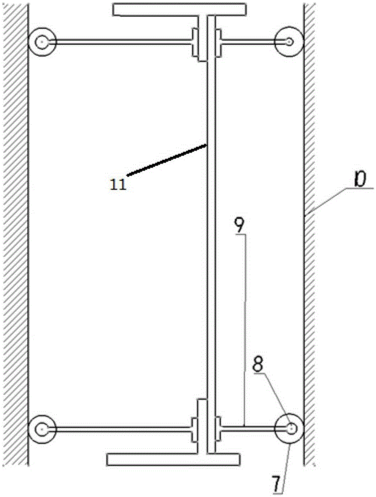
[0016] During the fatigue test, the load acts on the web beam test piece. Because of the roller 7, the anti-instability fixture can move in the web surface together with the test piece. When the plate is deformed outside the plane, the bracket 9 (rigid support rod) limits the out-of-plane deformation of the flange.


PUM


Abstract

The present invention belongs to the field of tooling design, and particularly relates to a web beam structure anti-destabilization clamper under a fatigue shear load effect. The web beam structure anti-destabilization clamper comprises a bracket 9, rollers 7 and clamping plates 10, wherein one end of the bracket 9 is the clamping end and the other end is the sliding end, the sliding end is connected to the rollers 7 through ball hinges 8, the clamping ends are fixedly connected to a web beam structure 11 from both sides, and the clamping plates are tightly matched with the rollers 7 from both sides, such that the clamping effect is provided for the whole clamper.

Description

technical field [0001] Book invention It belongs to the field of tooling design, specifically involving An Anti-Instability Fixture for Web Beam Structure Under Fatigue Shear Load . Background technique [0002] The web beam test piece is subjected to the fatigue shear load. For the test section, the beam web bears the shear force, and the upper and lower beam flanges are respectively subjected to tension and compression. On the one hand, under the action of compressive load, the beam flange may be laterally unstable. On the other hand, considering that the position of the loaded load may have a slight deviation from the section center of the test piece, additional torque will be generated on the test piece, resulting in torsional deformation. Therefore, in order to avoid the above-mentioned possible instability problems, it is necessary to install an anti-instability device. [0003] There are two kinds of anti-instability fixtures as follows: [0004] One structure is...

Claims


Application Information

Patent Timeline
IPC IPC(8): G01N3/04
Inventor 尚晓冬胡文刚刘志芳李良操徐海斌刘洁
Owner HARBIN
Learn More