
LED lamp with invisible radiating device

A technology of LED lamps and heat dissipation devices, which is applied in the direction of cooling/heating devices of lighting devices, lighting devices, lighting and heating equipment, etc., and can solve the problems of affecting the use effect and service life of lamps, high packaging and transportation costs, and slow heat dissipation and convection speed etc. to achieve good heat exchange performance, light weight, and fast heat dissipation

Pending Publication Date: 2017-02-15
刘骁洋
View PDF8 Cites 0 Cited by
  • Summary
  • Abstract
  • Description
  • Claims
  • Application Information

AI Technical Summary

Problems solved by technology

Considering the tightness requirements of the luminaire itself, the holes connected to the outside are usually small, and no matter the "in" or "out" of the convection is the hole, so the heat dissipation airflow needs to be detoured up and down, resulting in a slow heat dissipation convection speed, so The heat dissipation effect is also very limited, which greatly affects the use effect and service life of the lamp
In addition, for tubular lamps, because the lamp tube part needs to bear the heat generated by the luminous body in the lamp tube and ensure the lighting effect, the lamp tube made of glass is used, so the manufacturing cost is high, because the glass lamp tube is fragile. products, so the packaging and transportation costs are also higher

Method used


Image

  • LED lamp with invisible radiating device
  • LED lamp with invisible radiating device
  • LED lamp with invisible radiating device

Examples


Embodiment Construction

[0020] Best practice:

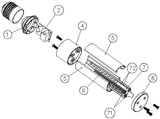
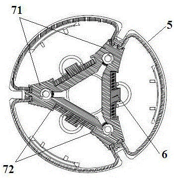
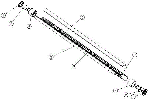
[0021] Refer to attached figure 1 , an LED lamp with an invisible heat dissipation device, including a lampshade 5, a luminous body 6, a lamp post 7 and a lamp holder 4, the lamp post 7 is a triangular column structure with three sides, each side is provided with a strip-shaped plug Groove, the elongated slot is composed of two parallel rail-type grooves 72 located on both sides of the side length direction. At this time, the illuminant 6 is a strip-shaped structure, specifically a The long plate-shaped structure is composed of a long plate and lamp beads installed on it. When installing, insert the long plate from one end of the long slot and slide it in along the rail grooves 72 on both sides. slot. The two sides of each side of the lamp post 7 respectively extend outward to form a lampshade connecting piece 71 , and the lampshade connecting piece 71 can be made into a guide rail groove.

[0022] combined with figure 2 , the lampshade 5 is compos...


PUM


Abstract

The invention relates to an LED lamp, in particular to an LED lamp with an invisible radiating device. The LED lamp with the invisible radiating device is structurally characterized in that a lamp pole is of a polygonal pole body structure and is provided with a plurality of side faces, and luminous bodies are installed on all the side faces; the two edges of each side face extend to form lamp cover connecting pieces; a lamp cover is composed of a plurality of sector cover bodies with the opening cross sections, and each sector cover body corresponds to one side face of the lamp pole; the two sides of the opening positions of the sector cover bodies are correspondingly connected with the lamp cover connecting pieces at the two sides of the side faces; each sector cover body and the lamp pole side face which is correspondingly connected with the sector cover body form a sector unit, a circular tube is formed by the surrounding multiple sector units and meanwhile gaps are reserved between every two adjacent sector units, and the gaps refer to ventilation and heat dissipation channels. Direct heat exchange of the lamp pole and the outside can be realized through the ventilation and heat dissipation channels, and meanwhile the ventilation and heat dissipation channels are hidden between every two adjacent sector units, so that the safety and operating requirement of the lamp pole are guaranteed. Hence, the heat dissipation speed is high, the heat dissipation effect is good, and the service life of the lamp is greatly prolonged.

Description

technical field [0001] The invention relates to an LED lamp, in particular to an LED lamp with an invisible cooling device. Background technique [0002] In the prior art, an LED lamp includes a lamp holder, a lamp bead column, a lamp driving circuit, a lamp holder and a lampshade. The lamp holder is connected to a power supply and connected to the lamp holder. Connect the power supply, and the other end is connected to the lamp bead board on the lamp bead post; the lamp bead post is located above the lamp holder and is fixedly connected with the lamp holder. The lampshade is a transparent or non-transparent shell that covers the lamp bead holder and connects Airtight connection. [0003] The lamp holder is often used as a heat sink for a lamp, and generally has cooling holes connected to the outside world to facilitate convective exchange of air inside and outside the lamp. However, this heat dissipation method is passive. The interior of the lamp is in a sealed state. Th...

Claims


Application Information

Patent Timeline
Patent Type & Authority Applications(China)
IPC IPC(8): F21K9/20F21V29/83F21Y115/10
CPCF21V29/83
Inventor 刘骁洋
Owner 刘骁洋
Learn More