
An automatic stamping machine

A technology of automatic stamping machine and swing rod, applied in printing, stamping and other directions, can solve the problems of laboriousness, certain requirements for paper size and high price

Active Publication Date: 2018-05-25
JINLING INST OF TECH
View PDF6 Cites 0 Cited by
  • Summary
  • Abstract
  • Description
  • Claims
  • Application Information

AI Technical Summary

Problems solved by technology

[0002] Although there are already some stamping machines on the market, after comparative analysis, it is found that the price of the machine that can realize automatic stamping is relatively high, and some of them cannot realize automatic paper feeding, and have certain requirements for paper size
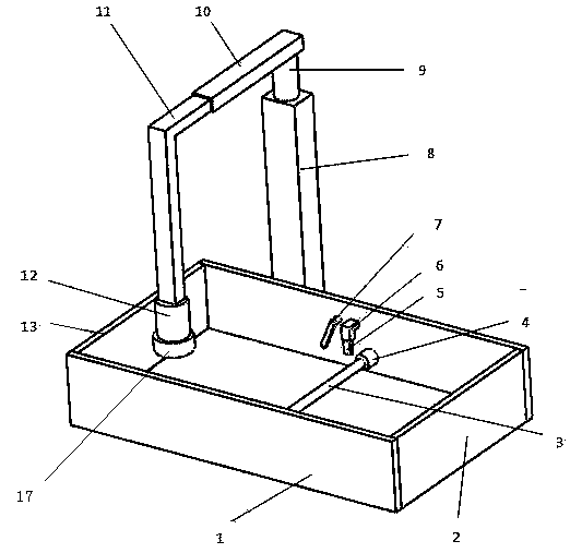
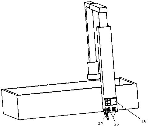
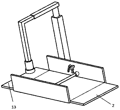
The lower-priced stamping machine also needs manual pressing. Although it can reduce the labor intensity of office workers, it is still relatively laborious when stamping in large quantities, such as when schools process admission notices, degree certificates, and graduation certificates.

Method used


Image

  • An automatic stamping machine
  • An automatic stamping machine
  • An automatic stamping machine

Examples


Embodiment Construction

[0012] The present invention will be further described in detail below in conjunction with the drawings and specific embodiments:

[0013] The invention provides an automatic stamping machine. After the stamping position is determined, through the combination of mechanical movement and control principle, the stamping gap is just running paper, and the next stamping action is performed after the paper is traveled, thereby realizing automatic stamping.

[0014] As an embodiment of the present invention, the present invention provides an automatic stamping machine, including a paper placement slot 1, a roller shaft 3, a roller 4, a paper sucking rod telescopic rod 5, a paper sucking rod fixing rod 6, and a paper swinging rod 7. , The vertical rod 8, the rotating shaft 9, the cross rod 10, the horizontal telescopic rod 11, the longitudinal telescopic rod 12, the power cord 14 and the chapter 17. There is a roller shaft 3 in the paper placing slot 1, and the two ends of the roller shaft ...


PUM


Abstract

The invention provides an automatic stamping machine. According to the application, a roller shaft is arranged in a paper placing groove, the side wall of the middle of the paper placing groove is provided with a paper sucking rod fixed rod, a paper sucking rod telescopic rod is arranged in the lower end of the paper sucking rod fixed rod, one side of the paper sucking rod fixed rod is provided with a paper shifting swinging rod, a motor of the paper shifting swinging rod is plugged on the inner wall of the paper placing groove, a vertical rod is fixed to the outer side of the paper placing groove, a rotating shaft is plugged at the upper end of the vertical rod, the end part of the rotating shaft is connected with a rotating shaft of a motor in the upper end of the vertical rod, the upper end of the rotating shaft is connected with the part below one end of a transverse rod, a transverse telescopic rod is plugged at the other end of the transverse rod, the end part of the transverse telescopic rod is connected with a cylinder in the transverse rod, the lower end of the bent part of the transverse telescopic rod is provided with a longitudinal telescopic rod, the upper end of the longitudinal telescopic rod is connected with a cylinder in the lower end of the bent part of the transverse telescopic rod, and a stamp is plugged in the lower end of the bent part of the transverse telescopic rod. After a stamping position is determined, through the combination of mechanical movement and a control principle, paper is precisely fed through a stamping clearance, and stamping action is carried out after the paper is fed, so that automatic stamping is realized.

Description

Technical field [0001] The invention relates to the field of intelligent office equipment, in particular to an automatic stamping machine. Background technique [0002] Although there are already some stamping machines on the market, after comparative analysis, it is found that the price of the machines that can realize automatic stamping is higher, and some of them cannot realize automatic paper feeding and have certain requirements for paper size. The lower-priced stamping machine also requires manual pressing. Although it can reduce the labor intensity of office workers, it is still more laborious when stamping in large quantities, such as when schools apply for admission notices, degree certificates, and graduation certificates. Therefore, it is necessary to design an automatic stamping machine to realize the automation of stamping. Summary of the invention [0003] In order to achieve high-efficiency automatic stamping, meet the requirements of various sizes of paper and var...

Claims


Application Information

Patent Timeline
Patent Type & Authority Patents(China)
IPC IPC(8): B41K3/04B41K3/62
CPCB41K3/04B41K3/62
Inventor 王锋锋
Owner JINLING INST OF TECH
Learn More