
Half shaft removal device and method for removing half shaft

A technology for dismantling devices and clamping parts, which is applied in the direction of manufacturing tools, clamps, hand-held tools, etc., can solve the problems of damage to the half shaft and gearbox, personal injury, inconvenient disassembly, etc., to achieve convenient use, labor-saving, and improved safety. , the effect of not easy to damage

Active Publication Date: 2018-11-06
BAIC MOTOR CORP LTD
View PDF6 Cites 0 Cited by
  • Summary
  • Abstract
  • Description
  • Claims
  • Application Information

AI Technical Summary

Problems solved by technology

[0004] Remove the half shaft through the crowbar. The prying process is affected by the end face of the moving joint of the half shaft and the shape of the gearbox. If the end face is uneven or the gearbox has no prying fulcrum, it will be inconvenient to disassemble; the crowbar is easy to slip during the prying process and cause personal injury; The force direction of the shaft does not coincide with the axis, and the prying process is easy to cause damage to the half shaft and gearbox

Method used


Image

  • Half shaft removal device and method for removing half shaft
  • Half shaft removal device and method for removing half shaft

Examples


Embodiment Construction

[0020] It should be noted that, unless otherwise specified, the technical terms or scientific terms used in this application shall have the usual meanings understood by those skilled in the art to which the present invention belongs.

[0021] In the description of the present application, it should be understood that the orientation or positional relationship indicated by the terms "length", "upper", "lower", "inner", "outer", "axial", "circumferential" etc. is Based on the orientation or positional relationship shown in the drawings, it is only for the convenience of describing the present invention and simplifying the description, and does not indicate or imply that the referred device or element must have a specific orientation, be constructed and operated in a specific orientation, and therefore cannot be understood To limit the present invention. In addition, the terms "first", "second", etc. are used for descriptive purposes only, and should not be understood as indicati...


PUM


Abstract

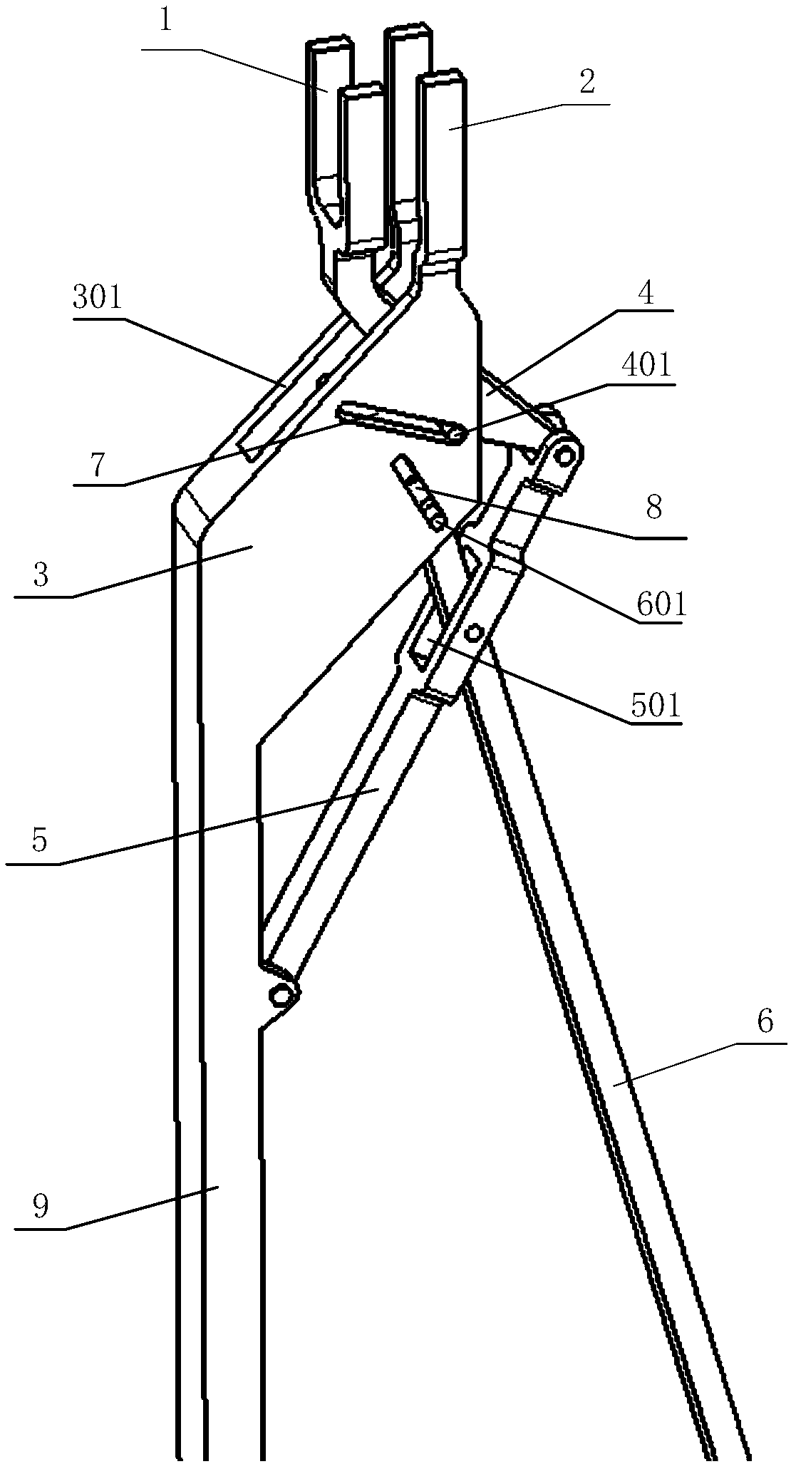
The invention provides a half shaft dismounting device and a method for dismounting a half shaft. The half shaft dismounting device comprises a first clamping part and a second clamping part for clamping the half shaft from the peripheral side surface, a second connecting arm which extends out from the first clamping part, a first connecting arm which extends out from the second clamping part, and a connecting rod drive device which is separately connected with the first connecting arm and the second connecting arm for driving the two clamping parts to relatively move, wherein the two clamping parts are parallel to each other. According to the half shaft dismounting device and the method for dismounting the half shaft provided by the invention, the two clamping parts clamp the half shaft from the peripheral side surface, and the connecting rod drive device drives the two clamping parts to move relatively, so that the half shaft is separated from a gearbox; in a relative moving process, the two clamping parts are kept to be parallel all the time, so that a half shaft moving joint is uniform and stable in stress, and damages on straightness of the half shaft are not caused in the axial direction of the half shaft, and therefore, the gearbox is not liable to deform; and moreover, use is not limited by the half shaft moving joint and the shape of the end surface of the gearbox, damages, on human bodies, of slippage are avoided, and therefore, the half shaft dismounting device is relatively safe, convenient and labor-saving.

Description

technical field [0001] The embodiments of the present invention relate to the field of automobile maintenance, in particular to a device for removing a half shaft and a method for removing a half shaft. Background technique [0002] The half shaft, also known as the constant speed drive shaft, is the shaft that transmits torque between the gearbox and the drive wheel. Its end inside the gearbox is generally connected to the differential gear of the gearbox through splines, and there is a shaft on the outside of the gearbox. The half-shaft movable joint, the half-shaft movable joint transmits the torque to the hub through a shaft rod and a fixed joint. [0003] In the prior art, dismounting the half shaft of the automobile is by inserting a crowbar into the gap between the moving joint of the half shaft and the gearbox, and pressing hard to separate the moving joint of the half shaft from the gearbox, thereby removing the half shaft. [0004] Use the crowbar to remove the ha...

Claims


Application Information

Patent Timeline
Patent Type & Authority Patents(China)
IPC IPC(8): B25B27/00B25B5/02B25B5/12
CPCB25B5/02B25B5/12B25B27/0035
Inventor 王磊
Owner BAIC MOTOR CORP LTD
Learn More