A gas spring relief valve

A gas spring, relief valve technology, applied in the direction of safety valve, balance valve, valve device, etc., can solve the problems of energy waste, affecting the service life of hydraulic system, etc., and achieve the effect of eliminating pressure regulation deviation

Active Publication Date: 2018-07-20
HUAQIAO UNIVERSITY
View PDF8 Cites 0 Cited by
  • Summary
  • Abstract
  • Description
  • Claims
  • Application Information

AI Technical Summary

Problems solved by technology

In the process of setting the pressure of the relief valve, the hydraulic system often works under high pressure and large flow conditions, which not only affects the service life of the hydraulic system, but also causes waste of energy

Method used


Image

  • A gas spring relief valve
  • A gas spring relief valve

Examples


Embodiment Construction

[0038] In order to further explain the technical solution of the present invention, it will be described in detail below in conjunction with the accompanying drawings.

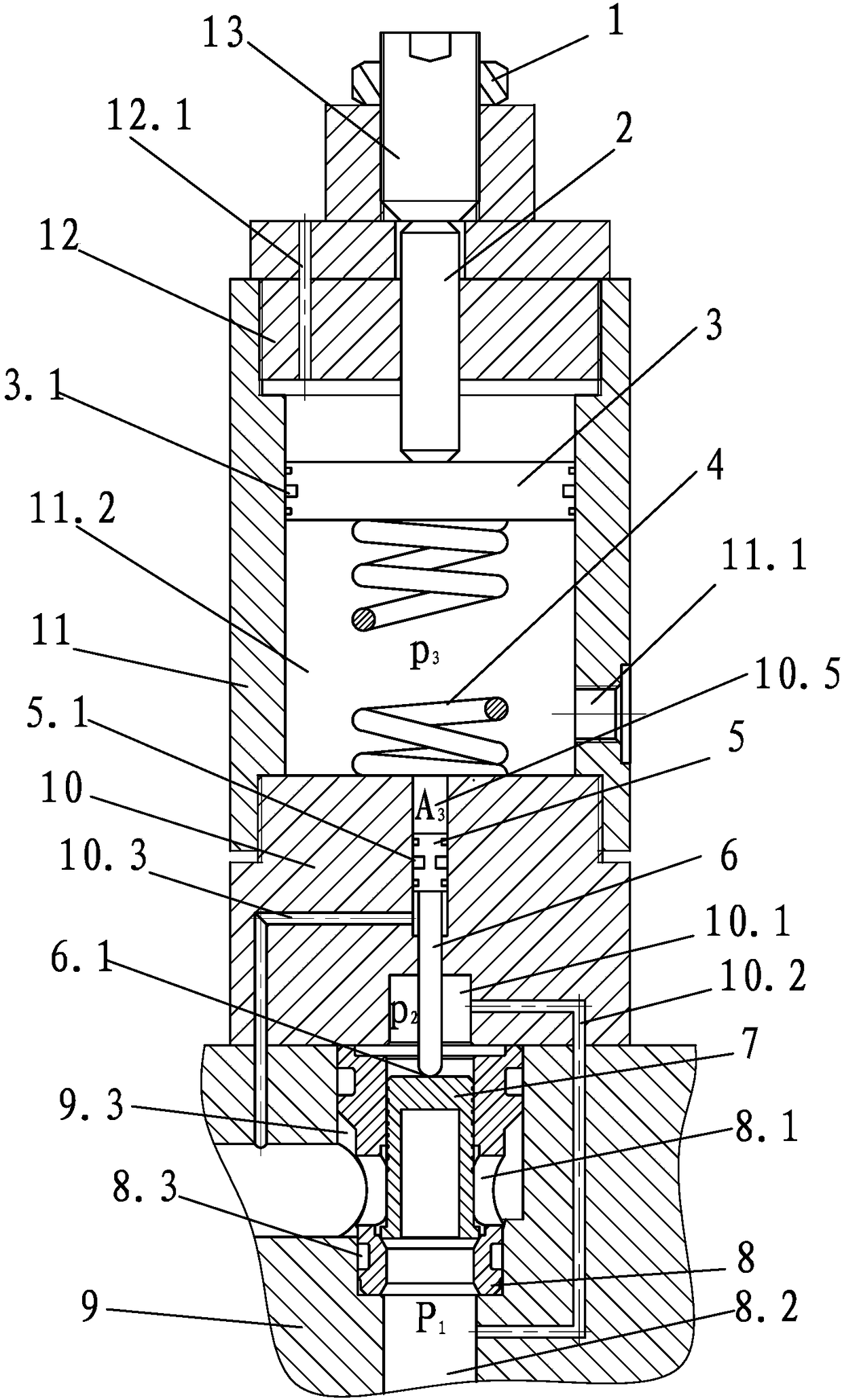
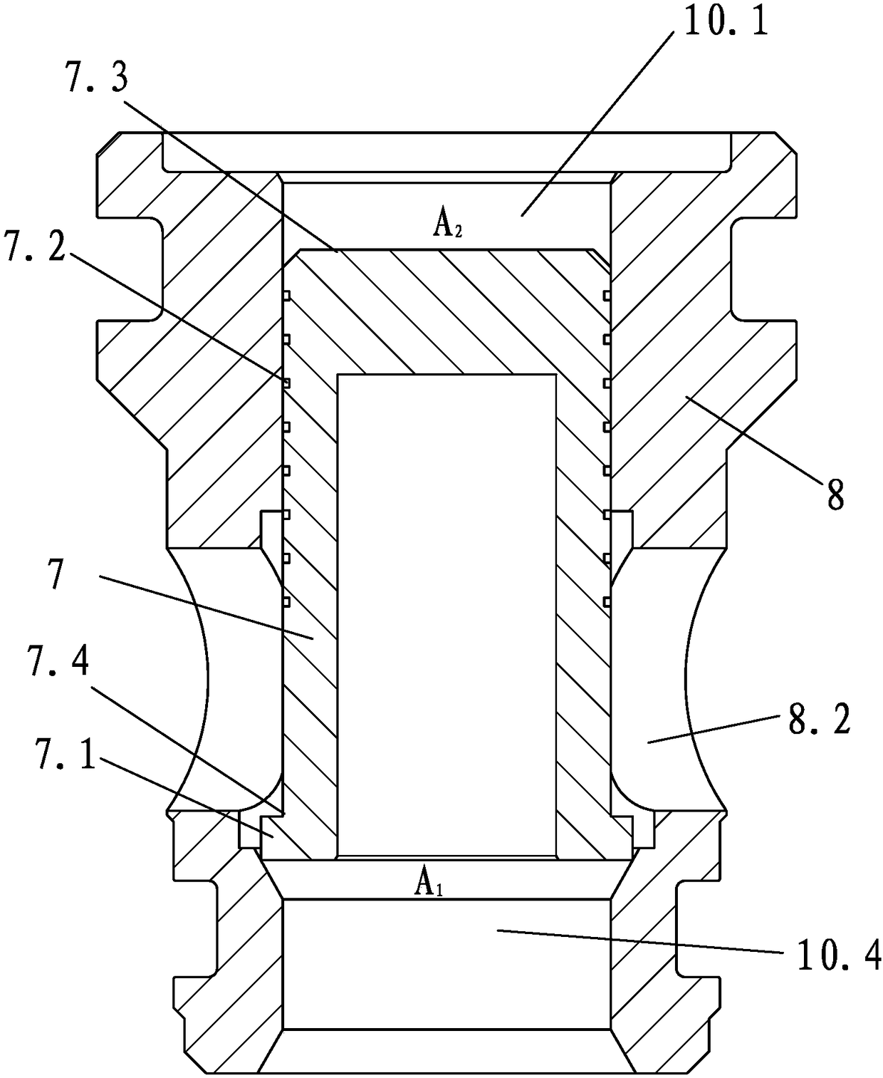
[0039] refer to figure 1 and figure 2 , a gas spring relief valve, including a valve seat 9, a valve chamber 9.3 disposed in the valve seat 9, a valve sleeve 8 disposed in the valve chamber 9.3, a valve core 7 slidably arranged in the valve sleeve 8 and The elastic pressing mechanism against the valve core 7 is provided with an oil inlet 8.2 and an oil outlet 8.1 connected with the valve cavity 9.3 on the valve seat 9. When the oil inlet 8.2 exceeds the set value, the oil will flow The spool 7 lifts up, and the oil flows out from the oil outlet 8.1.

[0040] In the present invention, the elastic pressing mechanism includes a cylinder body 11, a first valve body 12, a second valve body 10, a first piston 3 arranged in the cylinder body 11, and a valve body arranged between the first piston 3 and the second v...


PUM


Abstract

The invention discloses a gas spring overflow valve. The overflow valve comprises a limiting nut, a piston push rod, pistons, a spring, a valve core, a valve sleeve, a valve seat, a valve body and a piston cylinder. According to the gas spring overflow valve, two pistons with large diameter difference are arranged on the upper and lower ends of the gas spring, and the large piston which is located on the upper end is used for quickly establishing the internal pressure of the gas spring; the small piston which is located on the lower end is connected with the valve core of the overflow valve and is used for outputting thrust to the valve core of the overflow valve; and the diameter of the small piston is small, therefore, the change of the internal volume of the gas spring is small in the process that the valve core is opened, and the internal pressure of the gas spring can be basically kept constant, i.e. the thrust of the gas spring to the valve core can be kept constant all the time in the process that the valve core is opened. According to the gas spring overflow valve, clever structural design is utilized, so that the problem of large pressure adjustment deviation of a traditional indirect detection type overflow valve is effectively solved.

Description

technical field [0001] The invention relates to a gas spring overflow valve, which belongs to the field of electro-hydraulic control. Background technique [0002] The traditional direct-acting relief valve relies on setting the pre-compression of the pressure regulating spring to set the working pressure of the relief valve. As the overflow flow increases, the opening of the relief valve gradually increases, that is, the overflow The displacement of the valve spool gradually increases, the pressure regulating spring is further compressed, and the spring force acting on the spool increases, so the inlet pressure of the relief valve increases with the increase of the overflow flow, which makes the relief valve appear relatively large. A large pressure regulation deviation will have an adverse effect on the performance of the relief valve. Compared with the direct-acting relief valve, the pressure regulation deviation of the traditional indirect detection pilot relief valve i...

Claims


Application Information

Patent Timeline
Patent Type & Authority Patents(China)
IPC IPC(8): F16K17/32F15B20/00
CPCF15B20/005F16K17/32
Inventor 林添良缪骋陈强任好玲付胜杰陈其怀
Owner HUAQIAO UNIVERSITY
Why Eureka
Try Eureka