Pull rod guide type disc spring damper

A disc spring and damper technology, applied in the direction of spring/shock absorber, spring, low internal friction spring, etc., can solve the problems of disc spring deformation, increase of damper length, waste, etc., to prevent resonance and shorten the length. , The effect of reducing the cost of isolation

Active Publication Date: 2017-02-01
江苏天泽电力辅机有限公司
View PDF5 Cites 5 Cited by
  • Summary
  • Abstract
  • Description
  • Claims
  • Application Information

AI Technical Summary

Problems solved by technology

[0006] 1. The load connecting rod is kept balanced under the joint action of two sets of disc springs. Although the pre-tightening force of the two sets of disc springs can be adjusted, no matter how it is adjusted, the force of the two sets of disc springs on the load connecting rod will The acting forces are a set of equal and opposite forces, and simply applying any external force on the load connecting rod will break this balance and deform the two sets of disc springs, so the damper described cannot preset the early stiffness ;
[0007] 2. The damping coefficient of the disc spring is changed by preloading two sets of disc springs. This change is very limited, which leads to a small adjustment range of the equivalent stiffness of the damper, which often cannot meet the frequency requirements of building isolation;
[0008] 3. In this invention, two sets of disc springs must be used together to provide damping when the damper is under compression or tension load. This not only causes a certain amount of waste, but also greatly increases the length of the damper, which is not suitable for some Use where the installation space is tight
It can be seen that although the stiffness of the spring in the patent application scheme can be changed, the effective working length of the spring is not only significantly shortened, but also can only be compressed for energy consumption and vibration reduction, and cannot be stretched for energy consumption and vibration reduction.

Method used


Image

  • Pull rod guide type disc spring damper
  • Pull rod guide type disc spring damper
  • Pull rod guide type disc spring damper

Examples


example 1

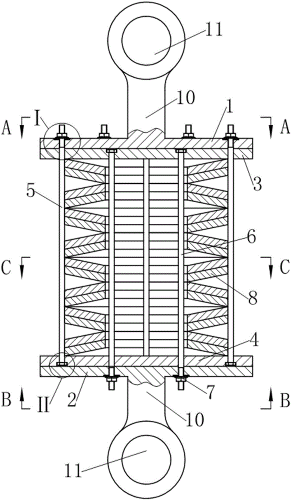
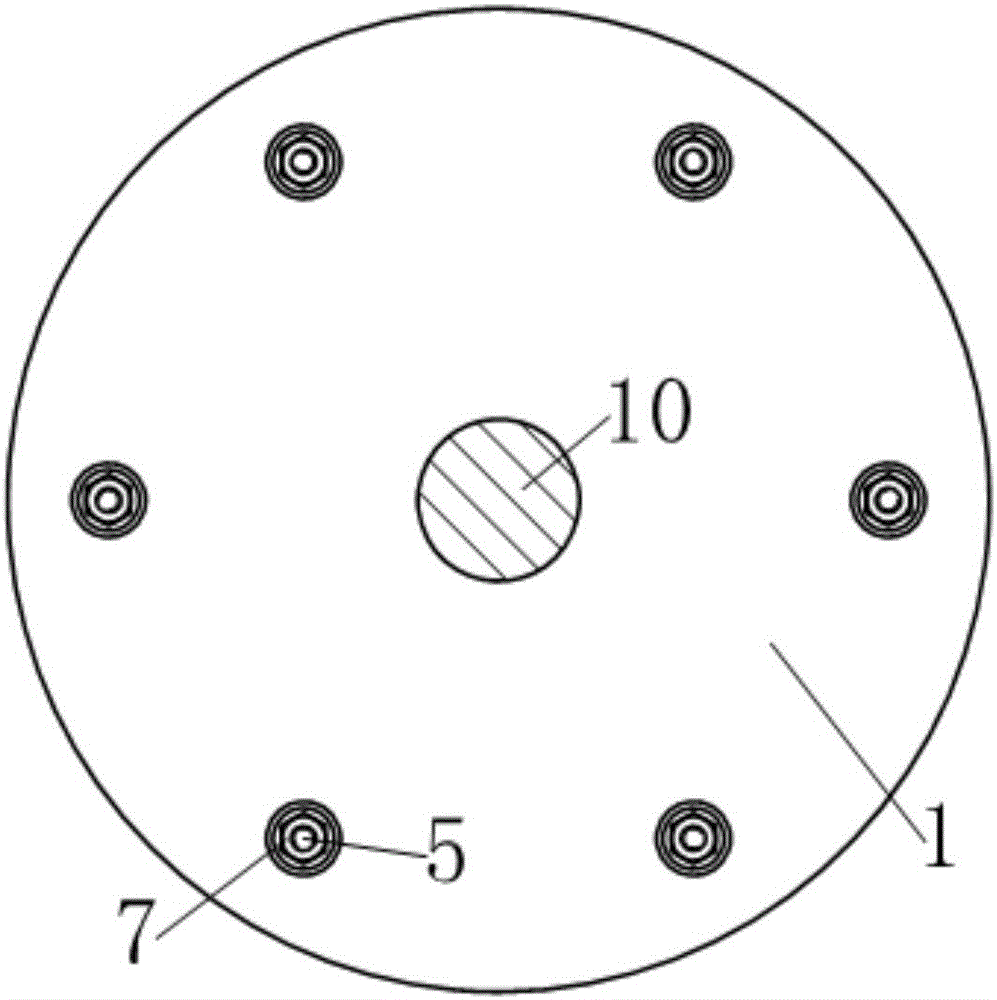
[0029] see figure 1 , the rod-guided disc spring damper in this example is an energy dissipation device that can be used for seismic reinforcement of building structures, and the damper includes two disc-shaped end plates, disc spring group 8 and back pressure device; Wherein, the disc spring group 8 is composed of 16 disc springs stacked vertically; the two end plates are the upper end plate 1 and the lower end plate 2 respectively located at the upper and lower ends of the disc spring group 8 . The upper surface of the upper end plate 1 and the lower surface of the lower end plate 2 respectively extend a connecting rod 10 along the axis of the disc spring group 8 to a direction away from the disc spring group 8, and the end of each connecting rod 10 is provided with a hinge hole 11.

[0030] see Figure 1~6 , the back pressure device includes two groups of polished rod bolts as pre-compression rods, two floating pressure plates and ten hexagonal flange nuts 7 as limiting e...

example 2

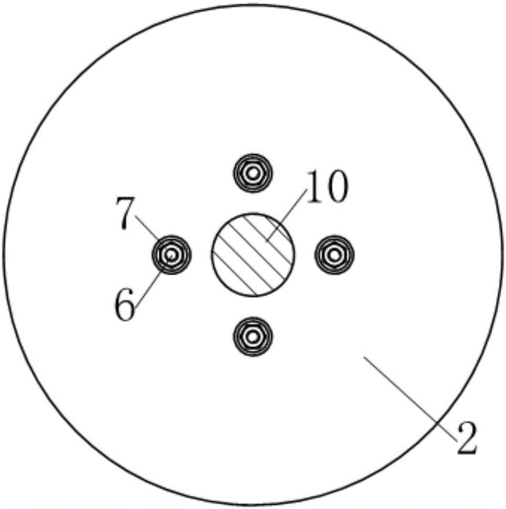
[0039] see Figure 7-10 , the rod-guided disc spring damper in this example is a vibration isolation device (also known as an isolation support) that can be used for vertical isolation of buildings. Compared with Example 1, this example mainly has the following differences:

[0040] 1. As a shock-isolation support, in order to facilitate installation, the connecting rods provided on the two end plates in Example 1 are omitted in this example, and the upper end plate 1 is extended axially upward and then radially outward from the edge. And the connecting bolt holes 12 are evenly provided at the edge; the lower end plate 2 is extended axially downward from the edge and then radially outward, and the connecting bolt holes 12 are evenly provided at the edge; the upper surface of the upper end plate 1 Between the upper end of the first group of polished rod bolts 5 and between the lower surface of the lower end plate 2 and the lower end of the second group of polished rod bolts 6, ...


PUM


Abstract

The invention discloses a pull rod guide type disc spring damper. The damper comprises two end plates, a disc spring set is arranged between the two end plates, and the damper is characterized in that a back pressure device is further arranged between the two end plates, and comprises two sets of pre-pressing pull rods and two floating pressing plates; the two floating pressing plates are arranged between one end plate and the disc spring set, the two sets of pre-pressing pull rods are parallel to the axis of the disc spring set, one set of pre-pressing pull rods are symmetrically distributed in a center hole of the disc spring set around the axis of the disc spring set, and the other set of pre-pressing pull rods are symmetrically distributed on the periphery of the disc spring seat around the axis of the disc spring set; one end of each set of pre-pressing pull rods is fixed to one floating pressing plate, and the other end of each set of pre-pressing pull rods penetrates the other floating pressing plate and the end plate adjacent to the other floating pressing plate to be fixed to a limiting element.

Description

technical field [0001] The present invention relates to shock absorbing devices, and in particular to dampers using disc spring sets. Background technique [0002] A damper is a shock-absorbing device that consumes motion energy by providing motion resistance. The use of dampers to absorb shock is a traditional technology widely used in industries such as aerospace, aviation, military industry, guns and automobiles. Since the 1970s, people have gradually applied the technology of using dampers to absorb and absorb shocks in structural engineering such as buildings, bridges, and railways. Disc spring dampers are widely used in various building anti-seismic structures due to their high impact resistance, low cost and good shock absorption effect. [0003] People pursue a comprehensive anti-seismic performance that combines "resistance" and "consumption" for the design of buildings, especially high-rise buildings, that is, under the action of weak wind vibration and small ear...

Claims


Application Information

Patent Timeline
Patent Type & Authority Applications(China)
IPC IPC(8): F16F7/00F16F3/02
CPCF16F3/023F16F7/00
Inventor 沈珊胡济福胡济全
Owner 江苏天泽电力辅机有限公司
Why Eureka
Try Eureka