Loop flushing systems for hydrostatic equipment
A hydrostatic and equipment technology, applied in the field of hydraulic loop flushing devices, can solve the problems that imply that the hydraulic system is damaged, hinder the optimal cooling of movable parts, and cannot establish a constant flushing flow, etc., and achieve the reduction in size and size Effect
- Summary
- Abstract
- Description
- Claims
- Application Information
AI Technical Summary
Problems solved by technology
Method used
Image
Examples
Embodiment Construction
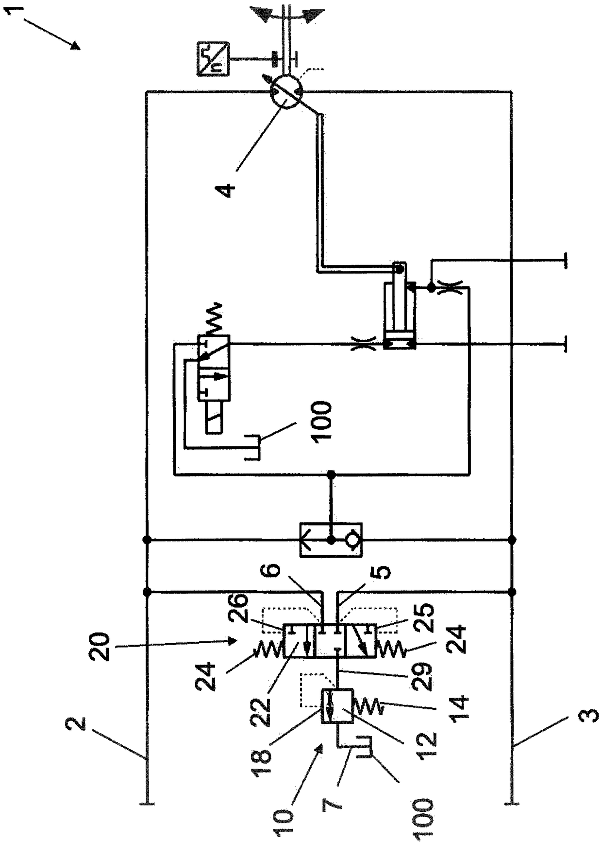
[0035] figure 1 A circuit diagram of a loop flushing system known from the prior art, for example the loop flushing system taught in US 6,430,923 B1, is schematically shown. In this system, each working line 2 and 3 of the hydrostatic propulsion system is led to one of the sensing diameters 25 or 26 of the shuttle valve spool 22 of the shuttle valve 20 . If the pressure difference between the high pressure side and the low pressure side produces a pressure on one of the sensing diameters 25 or 26 that is higher than the force of the shuttle valve spring 24 arranged on the opposite sensing diameter 26 or 25, the shuttle valve The spool 22 is moved so that the fluid connection to the passage 29 is opened for one of the inlet ports 5 or 6 (inlet port for low pressure). The fluid pressure generated in passage 29 in this manner is used to generate a cracking pressure against the force of flush valve spring 14 on sensing surface 18 of flush valve cartridge 12 of flush valve 10 . T...
PUM
 Abstract
Description
Claims
Application Information
 - R&D Engineer
- R&D Manager
- IP Professional
- Industry Leading Data Capabilities
- Powerful AI technology
- Patent DNA Extraction
Browse by: Latest US Patents, China's latest patents, Technical Efficacy Thesaurus, Application Domain, Technology Topic, Popular Technical Reports.
© 2024 PatSnap. All rights reserved.Legal|Privacy policy|Modern Slavery Act Transparency Statement|Sitemap|About US| Contact US: help@patsnap.com


