
Die for welding steel tube and sleeve and use method thereof

A technology for welding steel pipes and sleeves, applied in welding equipment, auxiliary welding equipment, welding/cutting auxiliary equipment, etc., can solve the problems of prolonging the construction period, difficult operation, and weak welding, so as to reduce the difficulty of construction and the scope of application Extensive, easy-to-control effects on welding quality

Active Publication Date: 2017-02-01
THE THIRD CONSTR OF CHINA CONSTR FIRST GROUP +1
View PDF7 Cites 1 Cited by
  • Summary
  • Abstract
  • Description
  • Claims
  • Application Information

AI Technical Summary

Problems solved by technology

At present, the welding of steel pipes is usually performed manually on site, which is difficult to operate and usually requires multiple people to operate at the same time, and it is prone to misalignment of steel pipes and weak welding, which causes a lot of waste of materials and prolongs the construction period.

Method used

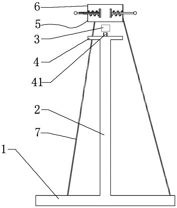
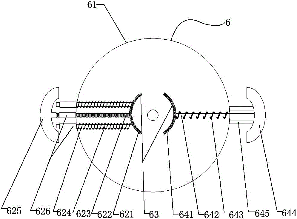

Image

  • Die for welding steel tube and sleeve and use method thereof
  • Die for welding steel tube and sleeve and use method thereof
  • Die for welding steel tube and sleeve and use method thereof

Examples


Embodiment

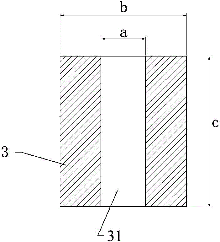
[0027] Such as figure 2 As shown, the dimensions of the socket head 3 in the mold for welding steel pipes and casing pipes of the present invention are shown in Table 1.

[0028] Table 1 Dimensions of sleeve

[0029] mmabc SC1510.0021.2533.50 SC2010.0026.7542.25 SC25 10.0023.37536.85

[0030] As shown in Table 1, a is the diameter of the hole 31 of the socket 3, b is the diameter of the socket 3, and c is the height of the socket 3.

[0031] The specific use method of the mold for welding steel pipes and casing pipes of the present invention is as follows:

[0032] According to the specifications of the welded steel pipe, select a suitable socket 3, tighten the socket 3 and the support column 2, insert the casing to be welded into the outer bottom of the socket 3. The inner diameter of the casing matches the outer diameter of the socket 3, and then The welded steel pipe is inserted into the casing and abuts against the top surface of the sleeve head 3. At this time, the bottom...


PUM


Abstract

The invention relates to the technical field of building steel tube connection and discloses a die for welding a steel tube and a sleeve and a use method of the die for welding the steel tube and the sleeve. According to the die for welding the steel tube and the sleeve, a base is fixed to the bottom end of a supporting column, an operation platform is fixed to the top end of the supporting column, a fixed screw rod is arranged at the center of the operation platform, the fixed screw rod is detachably connected with a sleeve head, a clamp is fixed to the position over the operation platform through a supporting rod in a suspended manner, the central axis of a clamp outer ring is horizontally arranged, and a clamping portion and a self-tightening portion are arranged along the diameter of the clamp outer ring; the top end of a threaded rod of the clamping portion supports a clamping sheet in a jacking manner, the tail end of the threaded rod of the clamping portion is fixed to a clamping handle, and fixed columns are sleeved with clamping springs; the top end of a self-tightening rod of the self-tightening portion is fixed to a self-tightening clamping sheet, the tail end of the self-tightening rod is fixed to a self-tightening handle, and the self-tightening rod is sleeved with a self-tightening spring; and two limiting columns are symmetrically arranged on the two sides of the self-tightening rod located outside the clamp outer ring correspondingly and are parallel to the self-tightening rod, and the two ends of each limiting column are fixed to the clamp outer ring and the self-tightening handle correspondingly. The die for welding the steel tube and the sleeve is simple in structure and easy and convenient to operate.

Description

Technical field [0001] The invention relates to the technical field of construction steel pipe connection, in particular to a mould for welding steel pipes and casing pipes and a method of use thereof. Background technique [0002] Welded steel pipe is a commonly used pipe material in the electrical construction process of buildings, and the amount is large. During the construction process, welding is required when connecting, and welding is time-consuming and welding quality is also an important link to ensure the subsequent procedures of the pipeline. At present, the welding of steel pipes usually adopts on-site manual welding, which is difficult to operate, usually requires multiple people to operate at the same time, and is prone to steel pipe misalignment and weak welding, which causes a lot of waste of materials and prolongs the construction period. Summary of the invention [0003] The technical problem to be solved by the present invention is to provide a mold for welding ...

Claims


Application Information

Patent Timeline
Patent Type & Authority Applications(China)
IPC IPC(8): B23K37/053
CPCB23K37/0533
Inventor 孙智君贾蒙袁小林邓展梅晓丽王红媛
Owner THE THIRD CONSTR OF CHINA CONSTR FIRST GROUP
Learn More