
Electric bicycle anti-falling auxiliary device driven by push rod motor

A push rod motor and auxiliary device technology, which is applied in the direction of motor vehicles, two-wheeled vehicle support devices, rider drives, etc., can solve the problems of large force required, discomfort in use, fatigue of one side of the leg, etc., and achieve load reduction , prolong the service life, easy and convenient to use

Active Publication Date: 2017-01-25
吴仁渭
View PDF6 Cites 5 Cited by
  • Summary
  • Abstract
  • Description
  • Claims
  • Application Information

AI Technical Summary

Problems solved by technology

Before the present invention was made, the existing electric vehicles had the following disadvantages during driving: when temporarily parking, both feet of the driver need to leave the foot-stepping area and extend to the ground to support the vehicle
[0005] During the driving process of the electric vehicle, the user will decelerate many times, and the number of riding stops will be less, and the user does not need the support wheel to touch the ground during the deceleration process, only when the user stops, the support wheel needs to be on the ground to prevent the electric vehicle from falling sideways , so the supporting wheels touch the ground every time they decelerate, but the electric vehicle does not completely stop moving forward, so that the supporting wheels wear out rapidly during the deceleration process
[0006] Secondly, stepping on the pedal with a purely mechanical structure causes the support wheel to support the ground, which requires a lot of force. If the user exerts force on one side for a long time, it is easy to make one leg weak and cause discomfort in use.

Method used


Image

  • Electric bicycle anti-falling auxiliary device driven by push rod motor
  • Electric bicycle anti-falling auxiliary device driven by push rod motor
  • Electric bicycle anti-falling auxiliary device driven by push rod motor

Examples


Embodiment Construction

[0041] The present invention will be further described below in conjunction with the accompanying drawings.

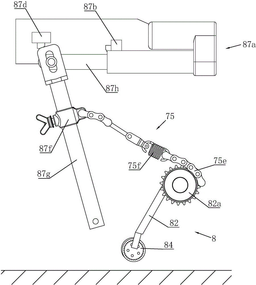
[0042] Such as Figures 1 to 6 Shown is an electric vehicle anti-falling auxiliary device driven by a push rod motor, including a power supply, a deceleration device, a control mechanism, a driving device and a support wheel 84;

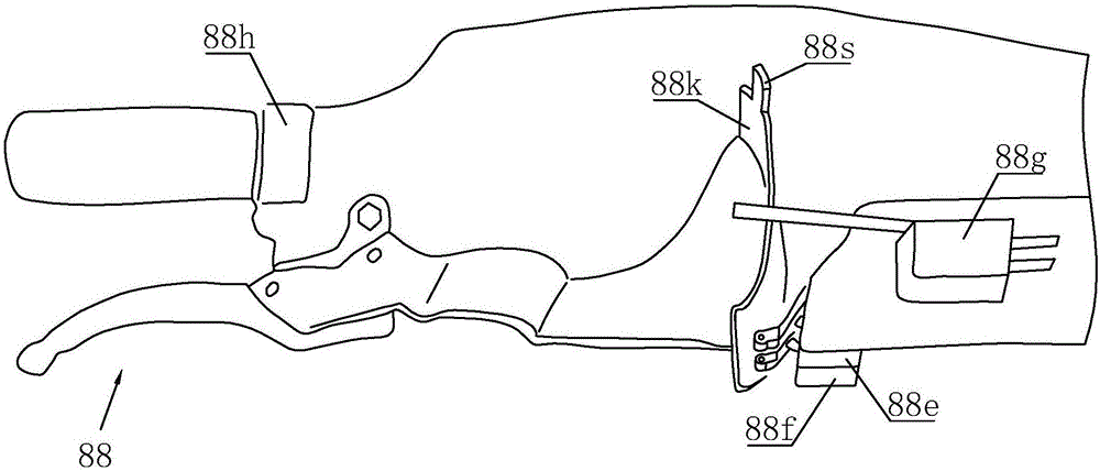
[0043] Reduction device: such as figure 1 As shown, the deceleration device includes an operating arm, and the operating arm uses a brake handle 88 as an operation control end; behind the brake handle is fixed a curved plate 88k for contacting the same stage start switch 88e and protection switch 88f, and behind the brake handle is also provided with a brake handle complete Can touch the push plate 88s of the second-order start switch 88g when gripping tightly, and the push plate 88s is positioned at the upper end of the bent plate 88k.

[0044] When decelerating, the brake handle 88 is held halfway for deceleration, and the curved plate 88...


PUM


Abstract

The invention discloses an electric bicycle anti-falling auxiliary device driven by a push rod motor. The electric bicycle anti-falling auxiliary device comprises a power supply, a speed reducing device, a control mechanism, a driving device and a support wheel, wherein an electric bicycle slightly brakes for deceleration, the driving device can enable the support wheel to downwards move a position near the ground; the support wheel only approaches to the ground but is not in contact with the ground; the abrasion of the support wheel is effectively prevented. When the electric bicycle completely brakes to the bottom, the support wheel completely touches the ground, so that the goal of preventing the lateral falling can be achieved through the ground supporting by the support wheel during temporary parking; the ground supporting by two feet of a user is not needed. The driving device is matched with a swinging rod through a push rod motor; a traction wire is connected onto the middle part of the swinging rod; by controlling the push rod motor, the swinging rod swings; the swinging rod is used for stretching and enabling the support frame to swing, so that the support wheel is driven to vertically move; the swinging rod uses a level principle; the load of the push rod motor is effectively reduced; the service life of the whole driving device is prolonged.

Description

technical field [0001] The invention belongs to an auxiliary anti-falling device for an electric vehicle driven by a push rod motor. Background technique [0002] With the gradual improvement of people's living standards, pedal electric bicycles (abbreviated electric vehicles) have become the most widely used daily means of transportation for people. Therefore, improving the safety performance of the vehicle and eliminating its potential safety hazards are closely related to millions of households. Before the present invention was made, the existing electric vehicles had the following disadvantages during driving: when temporarily parking, both feet of the driver need to leave the foot-stepping area and stretch out to the ground to support the vehicle. In this state, because the position supported by the feet has exceeded the width of the vehicle, it will cause some inconvenience to the driver: if it is rainy, the shoes and trousers will be wet by the rain and the water flow...

Claims


Application Information

Patent Timeline
IPC IPC(8): B62H1/00B62L3/02B62L3/04B62K23/08B62M6/45
CPCB62H1/00B62K23/08B62L3/026B62L3/04B62M6/45B62K2204/00B62H2700/00
Inventor 吴仁渭
Owner 吴仁渭
Learn More