A bionic underground digging robot

A robot and habitat technology, applied in the field of bionic robots, can solve the problems of low excavation and walking efficiency, and achieve the effects of high excavation efficiency, flexible movement and good work stability.

Inactive Publication Date: 2018-05-11
WUHAN UNIV OF SCI & TECH
View PDF2 Cites 0 Cited by
  • Summary
  • Abstract
  • Description
  • Claims
  • Application Information

AI Technical Summary

Problems solved by technology

In the above-mentioned patented technology, the excavating mechanism and the walking mechanism of the robot are in the same mechanism. When excavating or walking, only one limb is in the working state. The efficiency of digging and walking is low, and the soil produced by excavation still needs to be transported away by other equipment.

Method used


Image

  • A bionic underground digging robot
  • A bionic underground digging robot
  • A bionic underground digging robot

Examples


Embodiment 1

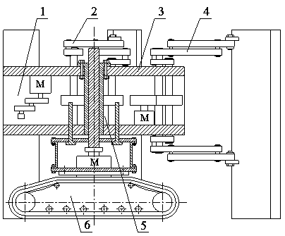
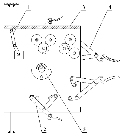
[0041] A bionic underground digging robot. Such as figure 1 and figure 2 As shown, the bionic underground excavation robot is composed of a crawler walking device 6 , a lifting mechanism 5 , a body 3 , two bucket mechanisms 4 , two bucket mechanisms 2 and two extrusion mechanisms 1 . For the sake of description respectively, it is assumed that the forward direction of the bionic underground excavating robot is the front, and the left side facing the forward direction is the left. Such as figure 1 and figure 2 As shown, the lifting mechanism 5 is fixed at the center position of the upper part of the crawler belt traveling device 6 , and the upper part of the lifting mechanism 5 is fixedly connected with the center position of the upper part of the body 3 . Bucket mechanism 4 is installed symmetrically on both sides of the body 3 front portion, bucket mechanism 2 is installed symmetrically on both sides of the body 3 middle portion, and extrusion mechanism 1 is symmetrical...

Embodiment 2

[0059] A bionic underground digging robot. Except following technical parameter, all the other are with embodiment 1:

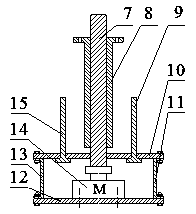
[0060] 3 or 5 small holes are evenly arranged near the threaded flange mounting hole 22, and the 3 or 5 small holes are located on the same circumferential line;

[0061] The flange is evenly provided with 3 or 5 small holes, and the 3 or 5 small holes are located on the same circumferential line. The 3 or 5 small holes of the threaded flange 8 are correspondingly connected with the 3 or 5 small holes provided on the body top plate 17 by bolts.

[0062] Compared with the prior art, this specific embodiment has the following positive effects:

[0063] The lifting mechanism of this specific embodiment is fixed at the center position of the upper part of the crawler belt traveling device, and the upper part of the lifting mechanism is fixedly connected with the center position of the upper part of the body; the bucket mechanism is symmetrically installed on bo...


PUM


Abstract

The invention relates to a bionic underground excavation robot. The technical scheme is that a lifting mechanism (5) is fixed to the central position of the upper portion of a crawler traveling device (6); the upper portion of a lifting mechanism (5) is fixedly connected with the central position of the upper portion of a body (3), bucket mechanisms (4) are symmetrically installed on the two sides of the front of the body (3), scraper pan mechanisms (2) are symmetrically installed on the two sides of the middle of the body (3), and extrusion mechanisms (1) are symmetrically installed on the two sides of the rear of the body (3). According to the bionic underground excavation robot, not only can the bucket mechanisms (4) and the scraper pan mechanisms (2) be utilized to perform earlier stage earth cutting work for urban underground pipe laying, but also the extrusion mechanisms (1) can be utilized to effectively squeeze soil to a hole wall, the carrying away of soil generated by excavation is avoided, and the excavation efficiency is high. The bionic underground excavation robot can achieve functions of earth cutting, soil dumping and soil squeezing simultaneously and have the advantages of being good in working stability and high in excavation efficiency and traveling flexibly.

Description

technical field [0001] The invention belongs to the technical field of bionic robots. In particular, it relates to a bionic underground digging robot. Background technique [0002] With the rapid development of urban construction in our country, the construction of urban underground engineering, especially underground pipeline network, is imminent. In the laying process of underground pipeline networks such as electric power and telecommunications, the construction method used is often the traditional surface excavation buried pipeline method, but this method not only affects traffic and interferes with people's normal life, but also when pipelines must be located in rivers, When railways and ground buildings pass through underground, they can only look at the ocean and sigh. [0003] In recent years, research on bionic mining robots has attracted the attention of technicians. For example, the "Bionic Mole Cricket Robot" (CN200510010008.7) patent technology, the front paw...

Claims


Application Information

Patent Timeline
Patent Type & Authority Patents(China)
IPC IPC(8): B62D55/06B25J5/00E21D9/00
CPCB25J5/00B62D55/06E21D9/00
Inventor 侯宇代陈超尹志朋代梦婉
Owner WUHAN UNIV OF SCI & TECH
Why Eureka
Try Eureka