
Ejection type edge coiling bending mold on the side of floating mandrel and usage method thereof

A technology of ejection and mandrel, applied in the direction of ejection equipment, metal processing equipment, forming tools, etc., can solve the problems of waste of funds, torsion, poor material retrieving effect, etc., and achieve easy operation, good material retrieving effect and simple structure Effect

Inactive Publication Date: 2017-01-25
FUZHOU UNIVERSITY
View PDF6 Cites 2 Cited by
  • Summary
  • Abstract
  • Description
  • Claims
  • Application Information

AI Technical Summary

Problems solved by technology

[0002] In the production of curved and round products, the round parts are wrapped tightly on the punch after bending and forming. In order to quickly take out the material, most manufacturers add a side slider to the mold, but the effect of this setting structure is very good. Poor, resulting in a lot of money wasted, while the existing device is prone to offset, twist and form waste products when rolling

Method used


Image

  • Ejection type edge coiling bending mold on the side of floating mandrel and usage method thereof
  • Ejection type edge coiling bending mold on the side of floating mandrel and usage method thereof

Examples


Embodiment Construction

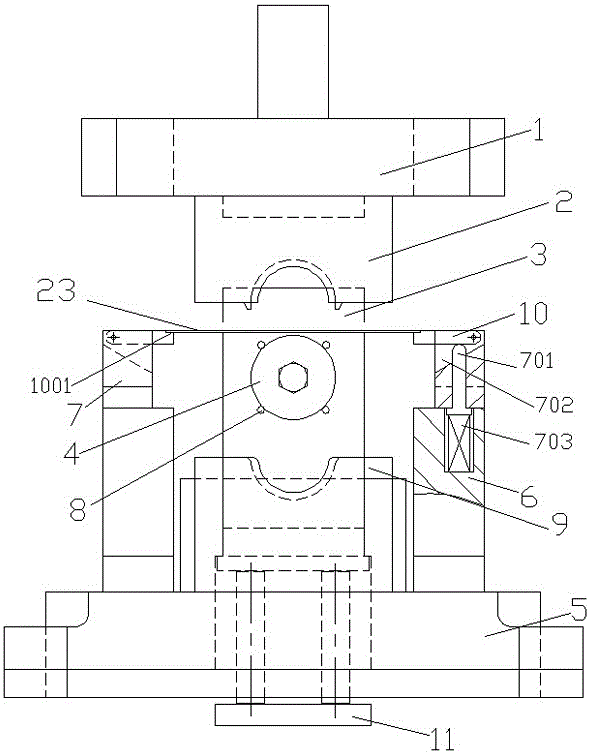
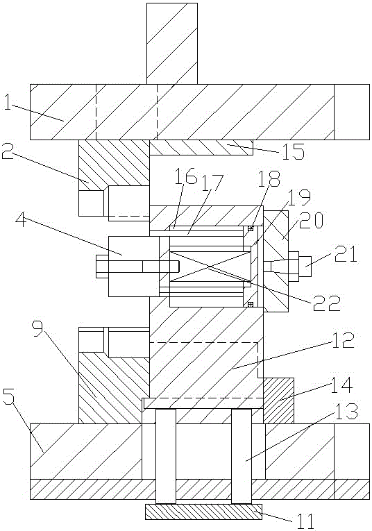
[0016] Such as Figure 1-2 As shown, a floating mandrel side has an ejection type roll bending die, including a punch seat 1 fixed on the upper die, a lower die seat 5 located below the punch seat 1, and a punch seat 1 The lower side is provided with a forming punch 2, the rear side of the forming punch 2 is provided with a pressing plate 15, and the upper side of the lower die holder 5 is provided with a forming lower die 9, and the forming lower die 9 is located directly below the forming punch 2 and is connected to the forming punch. 2 are matched together, the side of forming lower die 9 is provided with a discharge rack, the rear side of forming lower die 9 is provided with guide block 14, and guide block 14 is provided with a guide groove, and the guide groove is provided with a material that can move up and down relative to the lower die seat 5. The floating block 12 that moves, the floating block 12 is located below the pressing plate 15, the lower end of the floating ...


PUM


Abstract

The invention relates to an ejection type edge coiling bending mold on the side of a floating mandrel and a usage method thereof. The ejection type edge coiling bending mold comprises a puncher pin bearing seat and a lower mold bearing seat, wherein a forming puncher pin is arranged on the lower side face of the puncher pin bearing seat, a press plate is arranged on the rear side of the forming puncher pin, a forming lower die is arranged on the upper side face of the lower die bearing seat and is matched with the forming puncher pin, a discharging frame is arranged beside the forming lower die, a guiding block is arranged on the rear side of the forming lower die, a guiding groove is formed in the guiding block, a floating block is arranged in the guiding groove, a cylinder body is arranged at the upper end of the floating block, the mandrel is horizontally arranged at the front portion of the cylinder body and is located between the forming lower die and the forming puncher pin, a counter bored hole is formed in the rear portion of the cylinder body, a piston is arranged in the counter bored hole, an air cylinder cover is arranged at the rear end of the counter bored hole, horizontal pin holes are evenly distributed in the front end of the cylinder body and are located in the periphery of the mandrel, ejection pins penetrate into the horizontal pin holes, and the rear ends of the ejection pins are connected with the piston. By applying the floating mandrel, the problem that offsets or twisting easily occurs to cause scrap during edge coiling of a workpiece is solved, and a material taking effect is good by arranging lateral ejection structures.

Description

technical field [0001] The invention relates to a roll bending die with ejection on the side of a floating mandrel and a use method thereof. Background technique [0002] In the production of curved and round products, the round parts are wrapped tightly on the punch after bending and forming. In order to quickly take out the material, most manufacturers add a side slider to the mold, but the effect of this setting structure is very good. Poor, resulting in a lot of money wasted, while the existing device is prone to offset and twist during rolling, so as to form waste products. Contents of the invention [0003] The object of the present invention is to provide a type of roll bending die with ejection on the side of the floating mandrel and its application method. [0004] In order to solve the above-mentioned technical problems, a technical proposal of the present invention is that a floating mandrel side has an ejection type roll bending die, which includes a punch sea...

Claims


Application Information

Patent Timeline
IPC IPC(8): B21D37/10B21D45/04
CPCB21D37/10B21D45/04
Inventor 陈功振
Owner FUZHOU UNIVERSITY
Learn More