A new type of lumbar spondylolisthesis fixation and adjustable angle connecting rod
A connecting rod and angle-adjusting technology, which is applied in the field of medical devices, can solve the problems of difficulty in adapting to different types of bones, difficulty in controlling the bending angle, and inconvenient clinical use, so as to reduce sacrospinalis muscle damage, prevent vertebral body slippage, and achieve good results. The effect of curative effect
- Summary
- Abstract
- Description
- Claims
- Application Information
AI Technical Summary
Problems solved by technology
Method used
Image
Examples
Embodiment 1
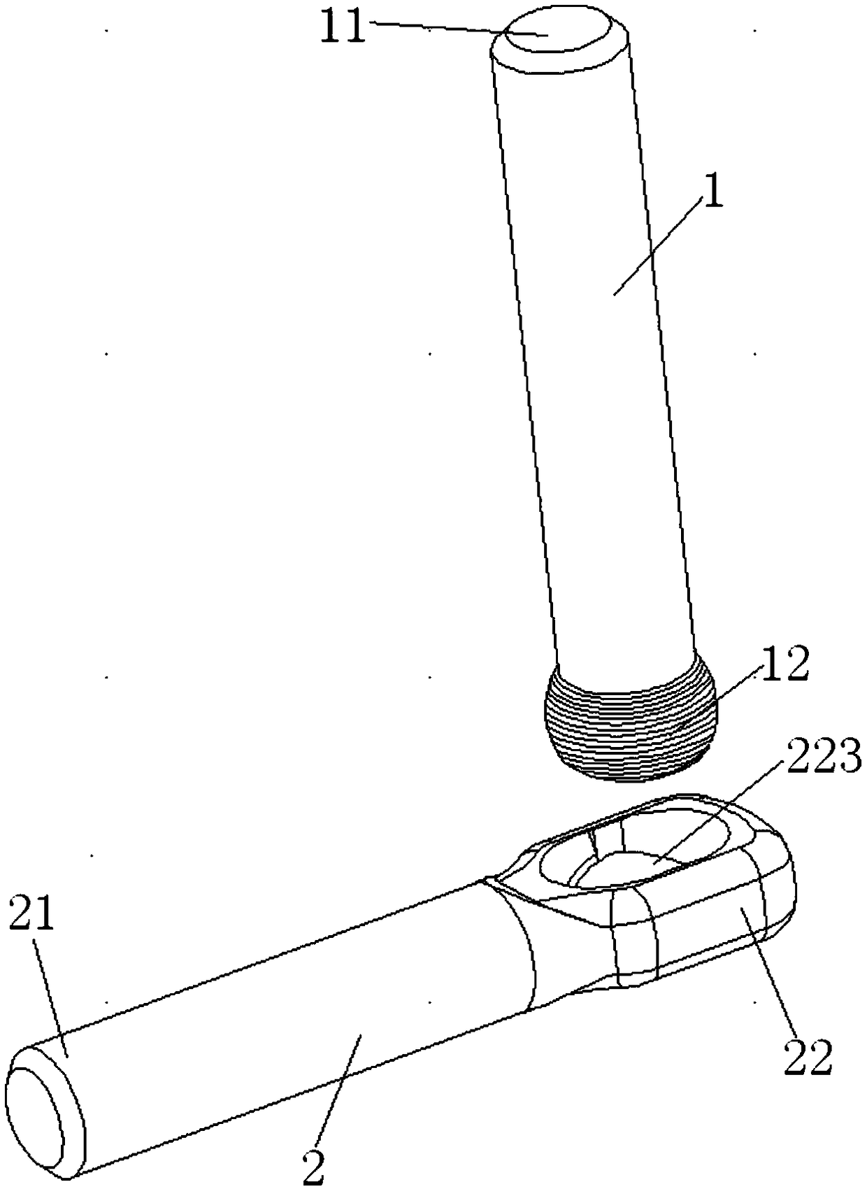
[0031] like figure 1 As shown, this embodiment provides a lumbar spondylolisthesis fixation adjustable angle connecting rod, including a first rod body 1 and a second rod body 2, the first rod body 1 and the second rod body 2 Connected into a V-shaped structure, and the V-shaped structure is set as a V-shaped structure with an adjustable angle.
[0032] The first rod body 1 includes a first end 11 and a second end 12 connected by a rod, the second rod 2 includes a first end 21 and a second end 22 connected by a rod, The second end portion 12 of the first rod body 1 and the second end portion 22 of the second rod body 2 are movably connected, so that the first rod body 1 and the second rod body 2 are connected at an angle Adjustable V-shaped structure.
[0033] In this embodiment, as figure 1 As shown, the second end portion 12 of the first rod body 1 is a ball joint, and the second end portion 22 of the second rod body 2 is connected to the second end portion 12 of the firs...
Embodiment 2
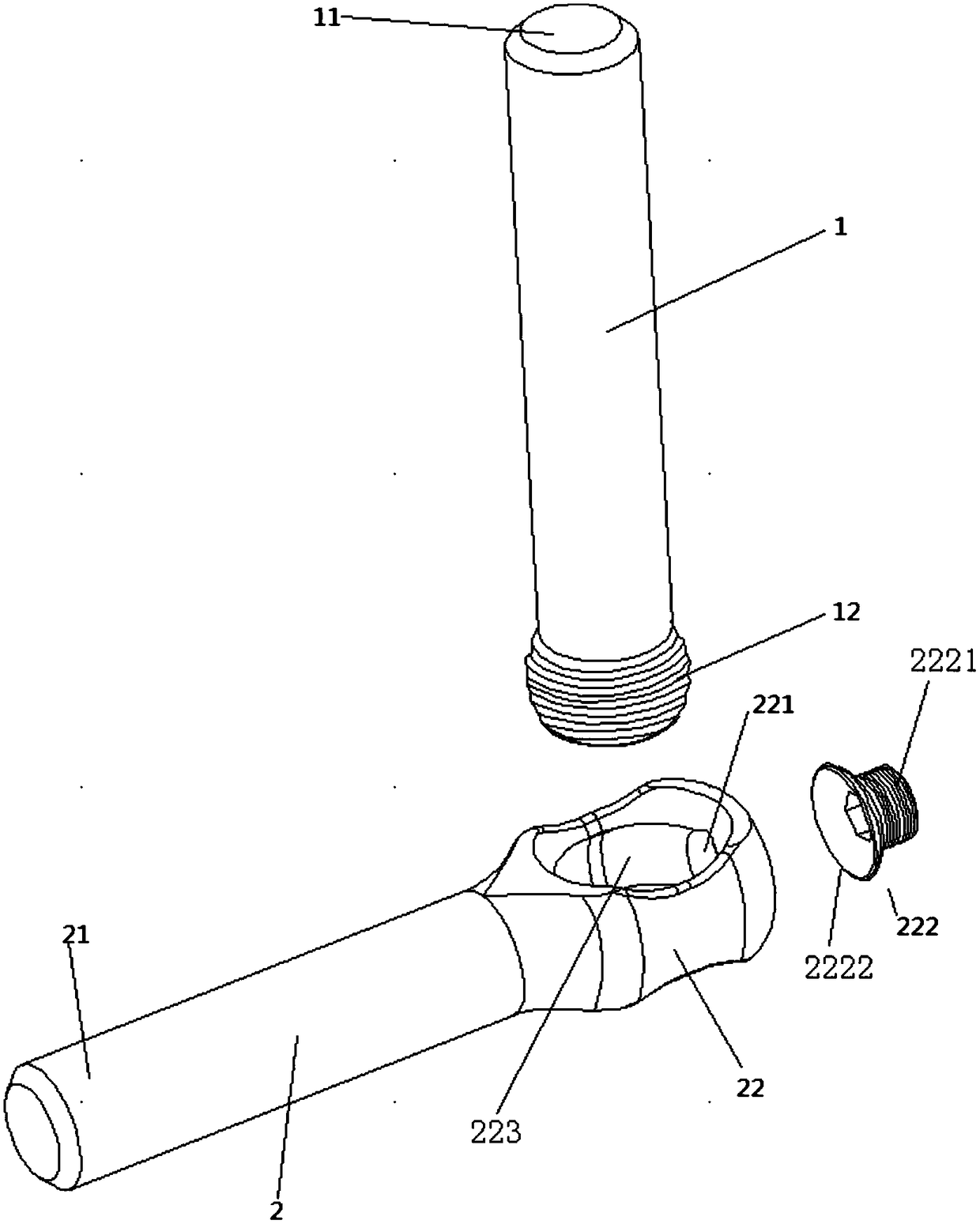
[0035] like figure 2As shown, the basic structure of a lumbar spondylolisthesis fixed and adjustable angle connecting rod of this embodiment is the same as that of Embodiment 1, except that the second end 22 of the second rod body 2 includes a limiting mechanism , the limiting mechanism is configured to limit the movement of the first rod body 1 relative to the second rod body 2 . In this embodiment, the limiting mechanism includes a threaded hole 221 provided on the second end 22 of the second rod body 2 and a screw 222 matched with the threaded hole 221 . The threaded hole 221 is disposed on the end face of the second end portion 22 and on the side wall of the through hole 223 . The threaded hole 221 has an inner thread, the screw 22 includes a screw rod 2221 with an external thread and an enlarged bottom end 2222, the diameter of the bottom end 2222 is larger than the diameter of the screw rod 2221, and the bottom end is just The concave spherical surface matched with th...
Embodiment 3
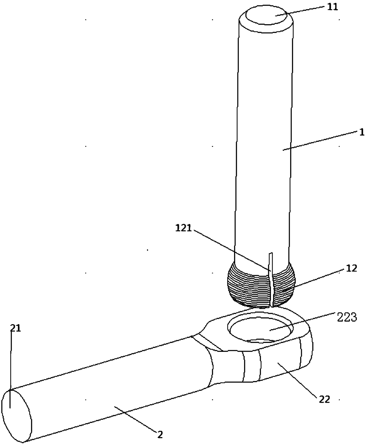
[0038] like image 3 As shown, the basic structure of a lumbar spondylolisthesis fixed and adjustable angle connecting rod of the present embodiment is the same as that of the first embodiment, the difference is that the joint with the concave spherical surface of the second rod body 2 is a joint with an inner concave spherical surface. For the through hole 223 of the concave spherical surface, the maximum inner diameter of the inner concave spherical surface is in the middle of the through hole 223, that is, the inner diameter of the two ends of the through hole 223 is smaller than the inner diameter of the middle of the through hole 223, and the inner diameter of the through hole 223 is from The two ends gradually become larger toward the middle, so that the through hole forms a concave spherical surface.
[0039] The ball joint of the second end 12 of the first rod body 1 is provided with a gap notch 121 along the axial direction of the rod body 1 , and the gap notch 121 di...
PUM
 Abstract
Description
Claims
Application Information
 - R&D Engineer
- R&D Manager
- IP Professional
- Industry Leading Data Capabilities
- Powerful AI technology
- Patent DNA Extraction
Browse by: Latest US Patents, China's latest patents, Technical Efficacy Thesaurus, Application Domain, Technology Topic, Popular Technical Reports.
© 2024 PatSnap. All rights reserved.Legal|Privacy policy|Modern Slavery Act Transparency Statement|Sitemap|About US| Contact US: help@patsnap.com


