
Imaging method and positioning device of X-ray imaging equipment

A technology of imaging equipment and imaging methods, which is applied in the fields of radiological diagnosis instruments, medical science, diagnosis, etc., can solve the problems such as the inability to determine the imaging position and the deviation of the area of ​​interest of the C-arm machine from the imaging field of view, so as to save the operation time, Streamline workflow and reduce the effects of repetitive actions

Active Publication Date: 2021-01-22
SHANGHAI UNITED IMAGING HEALTHCARE
View PDF5 Cites 0 Cited by
  • Summary
  • Abstract
  • Description
  • Claims
  • Application Information

AI Technical Summary

Problems solved by technology

[0003] The problem to be solved by the present invention is the problem that the region of interest deviates from the imaging field of view and the imaging position cannot be determined during the rotation of the C-arm machine

Method used


Image

  • Imaging method and positioning device of X-ray imaging equipment
  • Imaging method and positioning device of X-ray imaging equipment
  • Imaging method and positioning device of X-ray imaging equipment

Examples


Embodiment Construction

[0040] In order to make the above objects, features and advantages of the present invention more comprehensible, specific implementations of the present invention will be described in detail below in conjunction with the accompanying drawings. In the following description, specific details are set forth in order to provide a thorough understanding of the present invention. However, the present invention can be implemented in many other ways than those described here, and those skilled in the art can make similar extensions without departing from the connotation of the present invention. Accordingly, the present invention is not limited to the specific embodiments disclosed below.

[0041] Generally, in order to guide the operation during the operation, X-ray imaging equipment will be used to take pictures in real time to guide and confirm the operation process. The X-ray imaging device includes: an X-ray tube for emitting X-rays; a detector for receiving X-rays passing throug...


PUM


Abstract

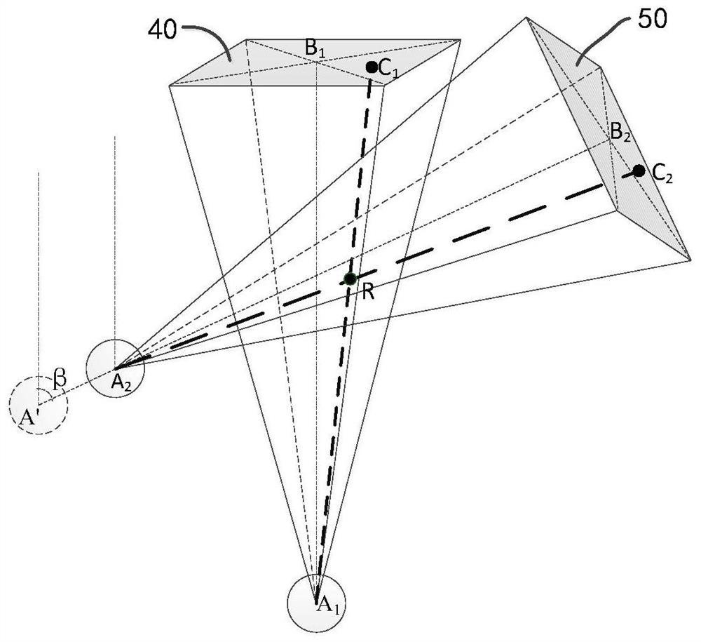
The invention provides an imaging method of X-ray imaging equipment. The X-ray imaging equipment comprises an X-ray bulb tube and a detector, and an imaging view exists between the X-ray bulb tube and the detector. The method is characterized by comprising the steps that an object to be detected is arranged in the imaging view; the object to be detected is imaged at at least two different positions, and images of the object to be detected are obtained; interested areas in the images are acquired; the space positions of the interested areas are calculated according to the interested areas in the images; the imaging position of the X-ray imaging equipment is adjusted according to the position relation between the space positions of the interested areas and the imaging view. According to the imaging position determining method, the position of an ROI in space can be acquired, the imaging position of the X-ray imaging equipment in any direction can be calculated according to the space position of the ROI, and it is guaranteed that the ROI is located within the imaging view range.

Description

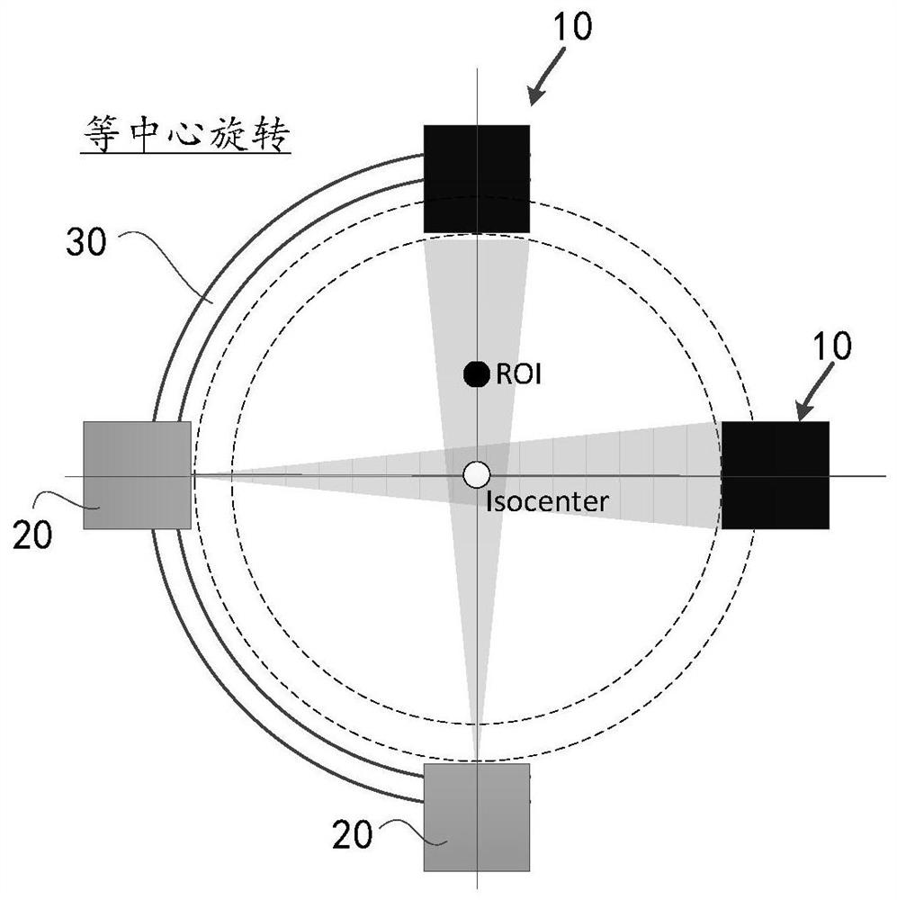
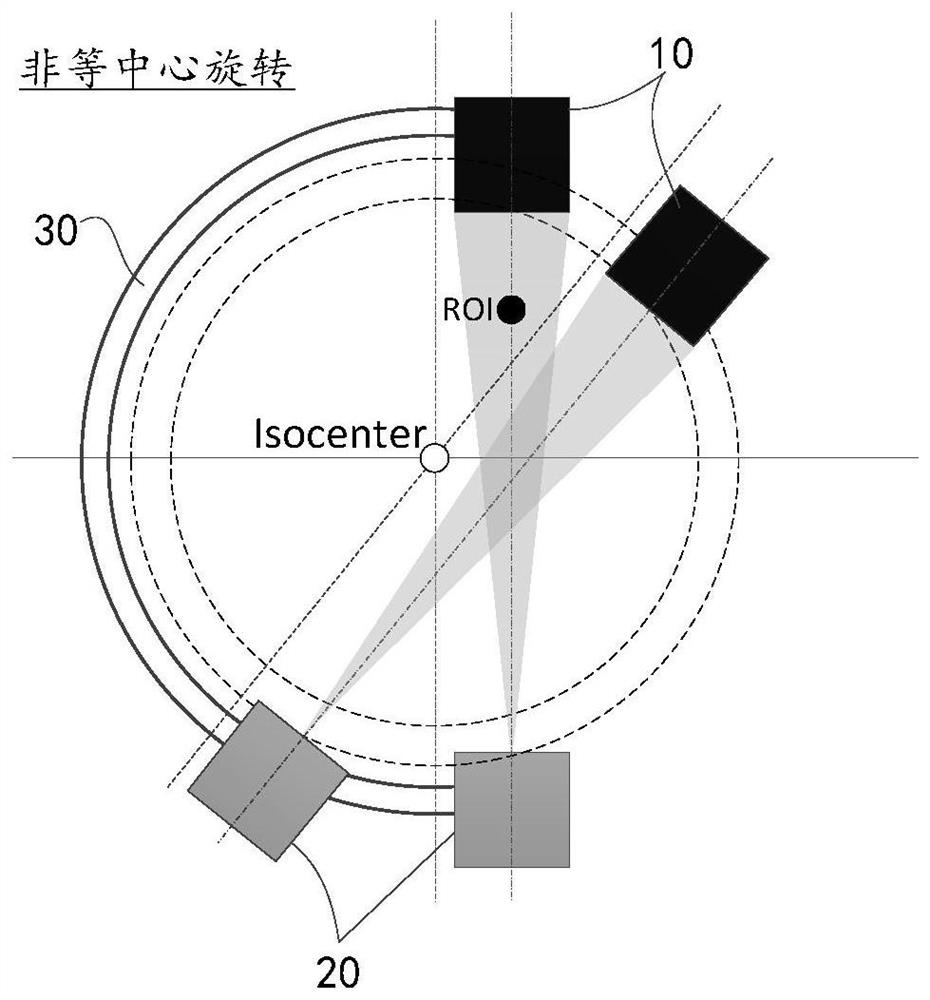
technical field [0001] The invention relates to the field of medical imaging equipment, in particular to a method and device for determining an imaging position of an X-ray imaging equipment. Background technique [0002] All current designs of C-arm machines, whether it is isocentric rotation or non-isocentric rotation, when the C-arm rotates, images at different positions will deviate to varying degrees. figure 1 is a schematic diagram of the rotation of the C-arm machine with isocentric rotation; figure 1 As shown, the isocenter rotation means that when the X-ray emitted by the X-ray emitting tube 20 is received by the detector 10, the center line of the beam formed between the two passes through the isocenter (Isocenter), and the process of the rotation of the C-arm machine The centerline of the beam described in , always passes through the isocenter. If the region of interest (hereinafter referred to as ROI) is not in the isocenter when the isocenter of the C-arm mach...

Claims


Application Information

Patent Timeline
Patent Type & Authority Patents(China)
IPC IPC(8): A61B6/00
CPCA61B6/00A61B6/4441A61B6/469
Inventor 虞倩倩
Owner SHANGHAI UNITED IMAGING HEALTHCARE
Learn More