
Cleaning device with cleaning roller with rotating bearing

A technology of cleaning equipment and rotating support, which is applied in cleaning equipment, cleaning machinery, carpet cleaning, etc., and can solve problems such as high manufacturing cost and inclination

Inactive Publication Date: 2017-01-25
VORWERK & CO INTERHOLDING GMBH
View PDF6 Cites 3 Cited by
  • Summary
  • Abstract
  • Description
  • Claims
  • Application Information

AI Technical Summary

Problems solved by technology

This results in relatively high manufacturing costs and the risk of tilting the projections when the cleaning roller is connected to the shaft

Method used


Image

  • Cleaning device with cleaning roller with rotating bearing
  • Cleaning device with cleaning roller with rotating bearing
  • Cleaning device with cleaning roller with rotating bearing

Examples


Embodiment Construction

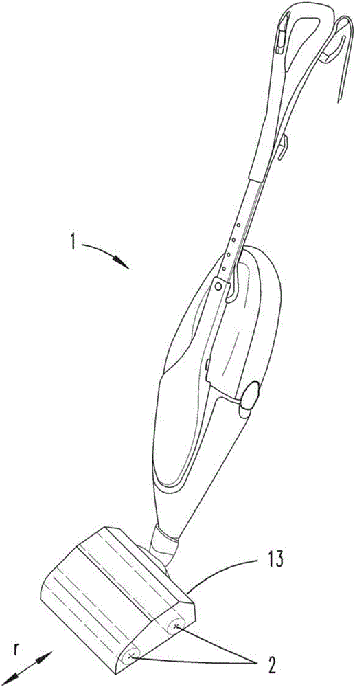
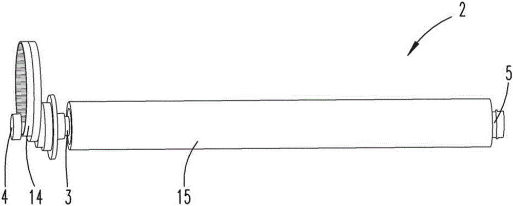
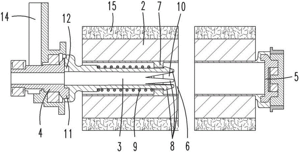
[0021] First follow figure 1 A cleaning device 1 in the form of a wet cleaning device for wet cleaning a surface to be cleaned is shown and described. The cleaning device 1 has an attachment device 13 which, during the cleaning process, comes into contact with the surface to be cleaned. The attachment device 13 here has, for example, two cleaning rollers 2 which can be loaded with liquid, in particular water. For this purpose, the cleaning roller 2 can be coated, for example, with a spray liquid or with a wetted roller coating 15 . The cleaning device 1 is supported on the surface to be cleaned by means of two cleaning rollers 2 . The cleaning roller 2 extends transversely to the usual direction of travel r of the cleaning device 1 which is caused by the usual working movement of the user of the cleaning device 1 , that is to say generally back and forth alternately, sometimes also slightly offset to the nearest parallel cleaning track. shift. The cleaning roller 2 here ex...


PUM


Abstract

The present invention relates to a cleaning apparatus (1), in particular a floor cleaning apparatus, which has a cleaning roller (2) with rotating bearing for cleaning the surface, and the cleaning roller (2) is provided with a roller driving part (3) co-rotating with a drive shaft on the apparatus side. The roller driving part (3) can be at least partially introduced in an axial roller gap (6) of the cleaning roller (2), wherein couplers (7, 8) capable of cooperating with each other is formed on the roller driving part (3) and the roller gap (6). In order to provide the cleaning apparatus (1), different fixing devices for the cleaning roller (2) are arranged on the drive shaft. In this way, the roller driving part (3) has a roller driving part spring (3), and the couplers (7, 8) are fixed mutually through the roller driving part spring under an installed state to transmit torque.

Description

technical field [0001] The invention relates to a cleaning device, in particular a floor cleaning device, with a rotatably mounted cleaning roller for cleaning surfaces, the cleaning roller being equipped with a roller drive for co-rotation with the side drive shaft of the device, the roller drive being able to At least partially inserted into the axial roller groove of the cleaning roller, and wherein a cooperating coupling element is formed on the roller drive and the roller groove. Background technique [0002] Cleaning devices of the above-mentioned type are known. It has one or more cleaning rollers, which can usually be loaded with a cleaning liquid and used for wet wiping of the surface to be cleaned. The cleaning roller is mounted rotatably inside the cleaning device. [0003] Document WO 1997 / 045052 A1 discloses a cleaning device, for example, with a tubular brush body into which the shaft of the cleaning device can be inserted. The rotationally fixed coupling of...

Claims


Application Information

Patent Timeline
Patent Type & Authority Applications(China)
IPC IPC(8): A47L11/22A47L11/40
CPCA47L11/22A47L11/40A47L11/4041A47L11/282A47L11/4069
Inventor B.林登贝克
Owner VORWERK & CO INTERHOLDING GMBH
Learn More