Aging test fixture
A technology for aging testing and fixtures, which is applied in the direction of power supply testing, measuring devices, and measuring electrical variables. It can solve problems such as deformation, ACPIN heat and force, etc., and achieve high test safety and more controllable power-on or power-off. Effect
- Summary
- Abstract
- Description
- Claims
- Application Information
AI Technical Summary
Problems solved by technology
Method used
Image

Examples
Embodiment 1
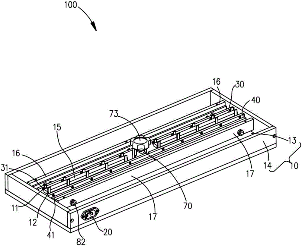
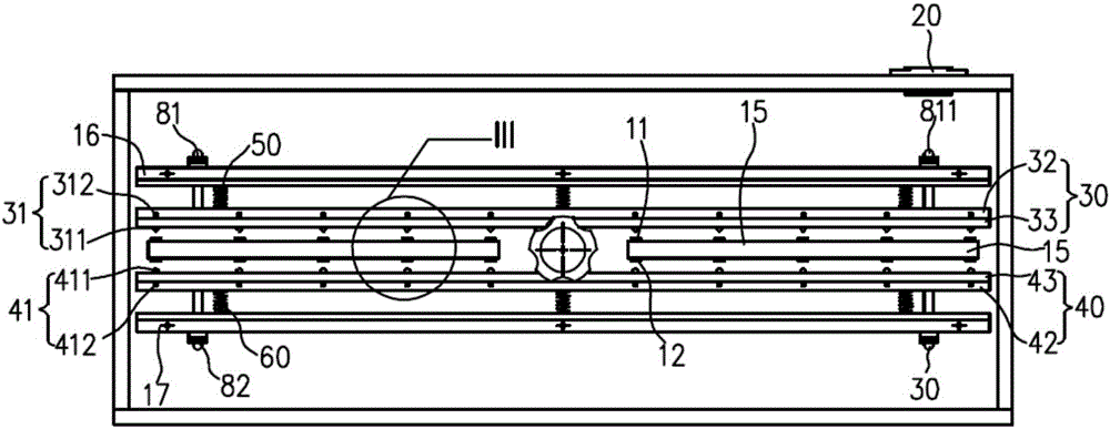
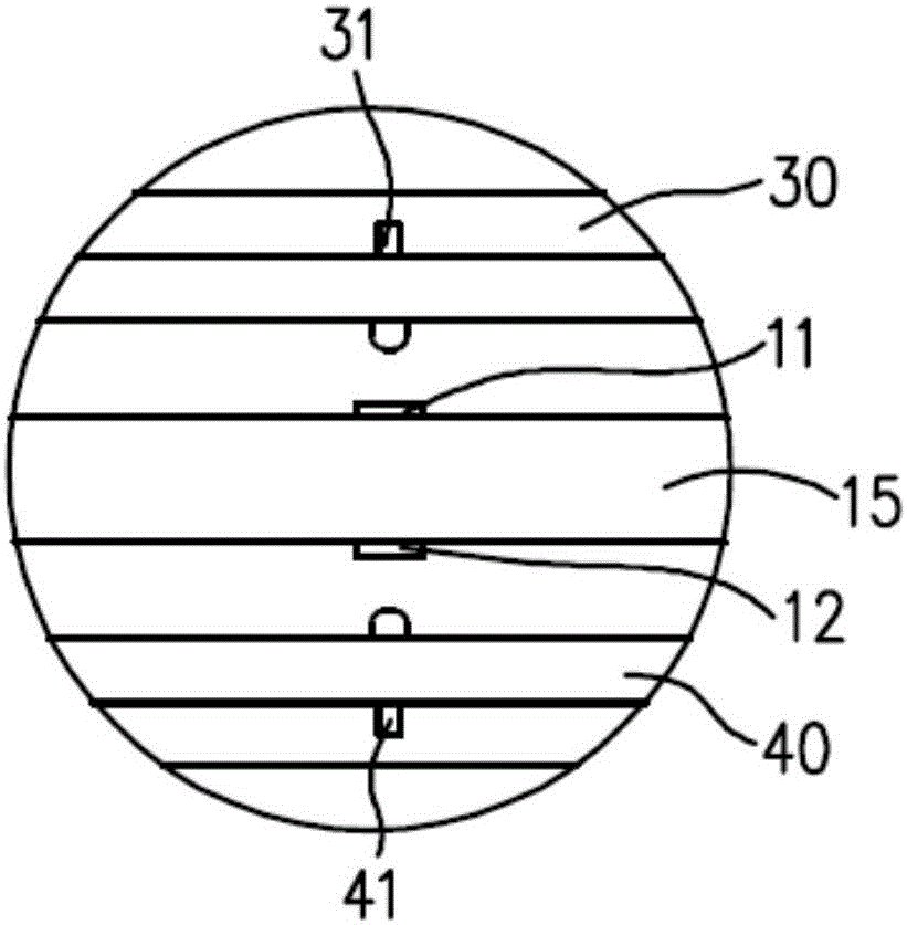
[0064] Please also refer to figure 1 , Figure 2 to Figure 7 , is a structural diagram of the jig 100 (with the cover plate and positioning parts omitted) provided in Embodiment 1 of the present invention.
[0065] In this embodiment, the above-mentioned base 10 is a square shell structure, including a bottom plate 13 and a side plate 14 surrounding the periphery of the bottom plate 13. The bottom plate 13 and the side plate 14 are enclosed to form a cavity structure. The first pin 11 and The second pins 12 are all disposed on the bottom plate 13 and located in the cavity structure, so that the overall structure of the jig 100 is more compact. It can be understood that, in other embodiments, the base 10 can also be a U-shaped shell structure or a circular shell structure.
[0066] Further, in order to ensure the user's testing safety, the base 10 can be made of insulating materials, such as plastic or glass.
[0067] In this embodiment, the power interface 20 is an external...
Embodiment 2
[0095] Please also refer to Figure 10 to Figure 11 , is a simplified structural diagram of the first limiting member 70 at the initial position and the preset position provided by Embodiment 2 of the present invention. The difference between Embodiment 2 of the present invention and Embodiment 1 of the present invention lies in:
[0096] A sliding slot (not shown) is defined on the base 10 , and the first limiting member 70 is slidably connected in the sliding slot. In this embodiment, the chute is a bar-shaped chute, and the two ends of the chute are respectively set corresponding to the initial position and the preset position, for example, when the first limiting member 70 is located at the first end of the chute , the first limiting member 70 is at the initial position, and when the first limiting member 70 slides to the second end of the chute, the first limiting member 70 reaches the preset position.
[0097] Since in this embodiment, the first limiting member 70 does...
Embodiment 3
[0104] Please also refer to Figure 12 to Figure 13 , is a simplified structural diagram of the first limiting member 70 at the initial position and the preset position provided by Embodiment 3 of the present invention. The difference between embodiment three of the present invention and embodiment two is:
[0105] Both the first elastic member 50 and the second elastic member 60 are two, one end of the two first elastic members 50 is connected to the first strip 30, the other end is connected to the side wall of the base 10, and the two first elastic members The pieces 50 are respectively arranged symmetrically on both sides of the first limiting piece 70; one end of the two second elastic pieces 60 is connected to the second strip 40, and the other end is connected to the side wall of the base 10, and the two second elastic pieces 60 The pieces 60 are arranged symmetrically on both sides of the second limiting piece 15 and opposite to the two first limiting pieces 70 . Spe...
PUM
 Abstract
Description
Claims
Application Information
 - R&D
- Intellectual Property
- Life Sciences
- Materials
- Tech Scout
- Unparalleled Data Quality
- Higher Quality Content
- 60% Fewer Hallucinations
Browse by: Latest US Patents, China's latest patents, Technical Efficacy Thesaurus, Application Domain, Technology Topic, Popular Technical Reports.
© 2025 PatSnap. All rights reserved.Legal|Privacy policy|Modern Slavery Act Transparency Statement|Sitemap|About US| Contact US: help@patsnap.com