
A kind of perforation drilling device and method in vertical drilling

An in-hole and vertical technology, applied in directional drilling, supporting devices, drilling equipment, etc., can solve the problems of complex technology, drilling without devices, and poor operability, so as to avoid complexity, facilitate storage, and facilitate adjustment Effect

Active Publication Date: 2018-05-29
CHINA UNIV OF PETROLEUM (EAST CHINA)
View PDF7 Cites 0 Cited by
  • Summary
  • Abstract
  • Description
  • Claims
  • Application Information

AI Technical Summary

Problems solved by technology

The technology of this method is relatively complicated, the drilling time is not easy to grasp, the operability is poor, and the drilling accuracy is not high, which will adversely affect the test results
[0004] In addition, in the current living and other projects, it is also necessary to drill horizontal boreholes in vertical boreholes, but there is no suitable device for drilling

Method used


Image

  • A kind of perforation drilling device and method in vertical drilling
  • A kind of perforation drilling device and method in vertical drilling
  • A kind of perforation drilling device and method in vertical drilling

Examples


Embodiment 1

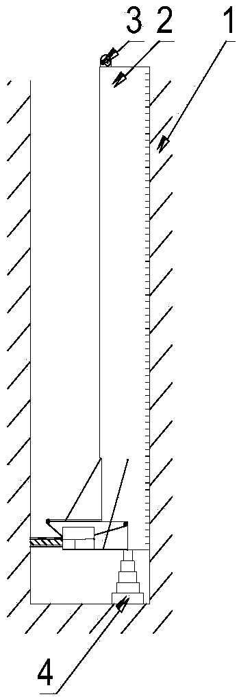
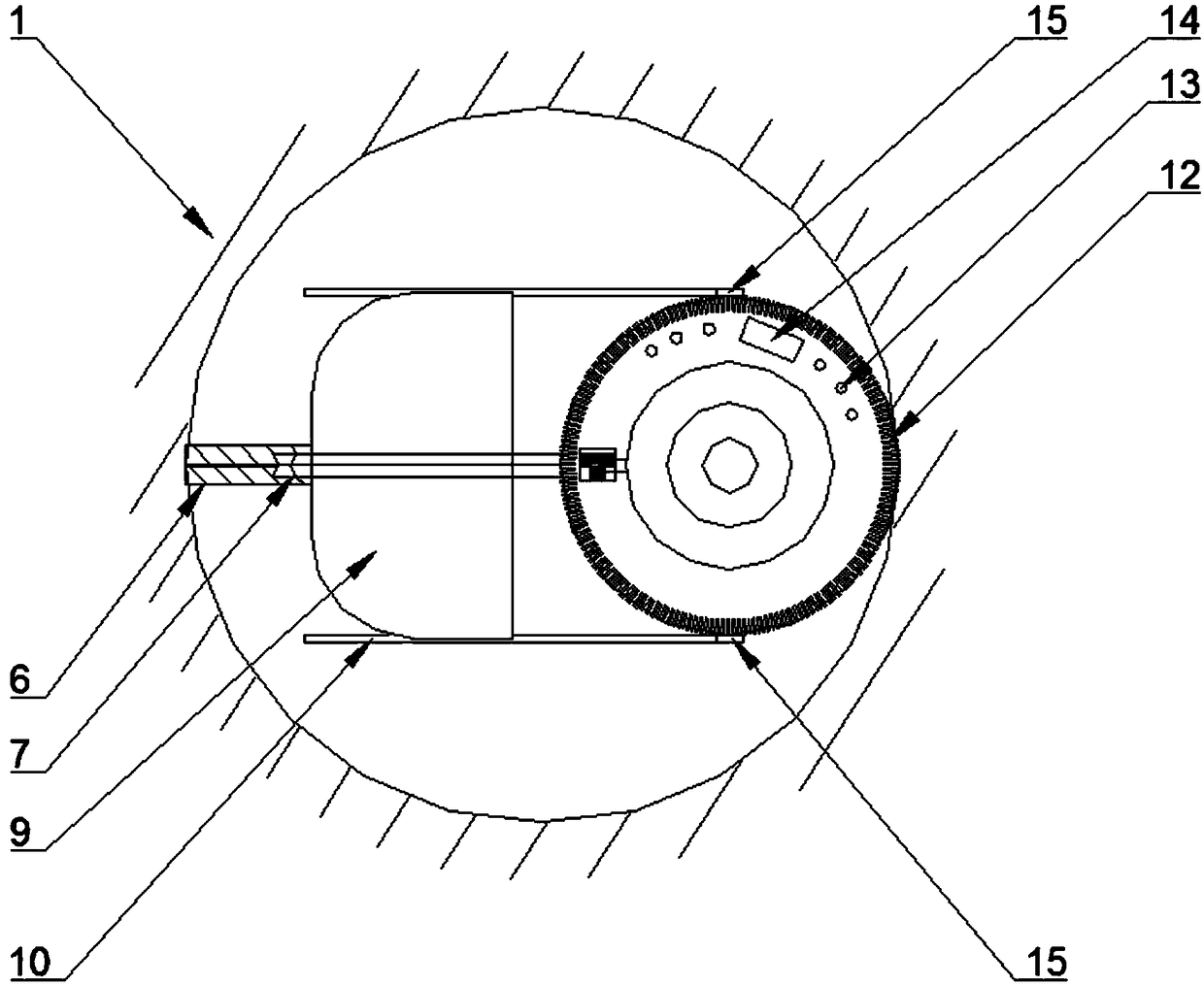
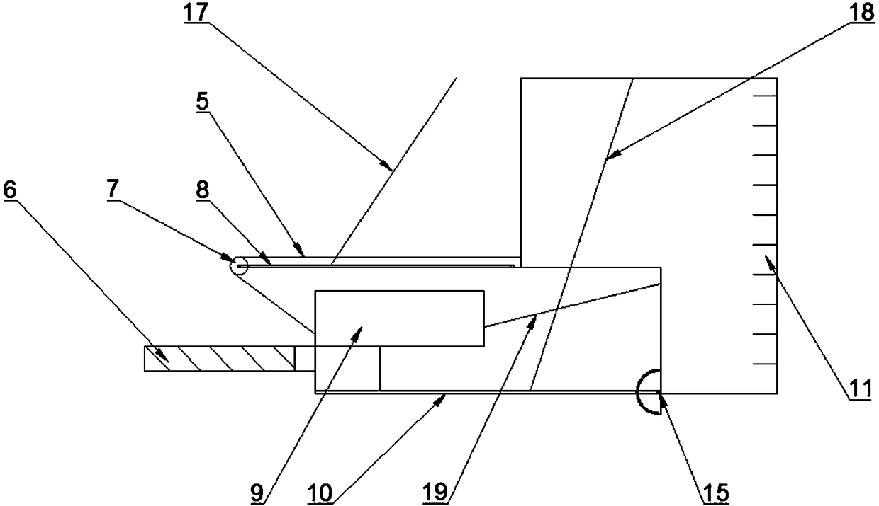
[0044]A perforation drilling device in a vertical borehole, comprising a metal hollow cylinder 2 that can be placed in a vertical borehole 1, a support member 4 is provided at the bottom of the hollow cylinder 2, an opening is opened on one side of the bottom of the hollow cylinder 2, and a A slideway 10 with one end hingedly connected to the bottom of the hollow tube 2 is provided inside, so that the slideway 10 can rotate up and down in the vertical plane of the opening. 10 sliding; one end of the drilling machine 9 drill bit is connected with the first wire rope 5 on the first hoist 3, and the first hoist rotates to drive the drilling machine 9 to advance on the slideway 10 through the first wire rope 5 to drill holes, and the other end of the drilling machine is connected to the second wire rope 5. The second wire rope on the hoist is connected, and the second hoist is rotated to drive the rig to retreat on the slideway through the second wire rope. A support cover can be ...

Embodiment 2

[0063] A perforation drilling device in a vertical borehole, comprising a hollow cylinder that can be placed in the vertical borehole, a support member is provided at the bottom of the hollow cylinder, an opening is opened on one side of the bottom of the hollow cylinder, and one end and a hollow cylinder are arranged in the opening. The slideway hingedly connected at the bottom of the cylinder, the drilling rig with the drill bit is set on the slideway and the drilling machine can slide along the slideway; one end of the drilling rig is connected or contacted with the propulsion mechanism at the bottom of the hollow cylinder, and the action of the propulsion mechanism drives the drilling rig to advance on the slideway Drilling is carried out, and the end of the drilling machine is connected with the second wire rope on the second hoist, and the second hoist is rotated to drive the drilling machine back on the slideway through the second wire rope.

[0064] The propulsion mecha...


PUM


Abstract

The invention discloses a perforation drilling device and method in a vertical borehole. The device includes a hollow cylinder that can be placed in the vertical borehole. A supporting part is provided at the bottom of the hollow cylinder. There is a slideway hingedly connected with the bottom of the hollow cylinder in the opening, the drill with the drill bit is arranged on the slideway and the driller can slide along the slideway; one end of the drill bit of the driller is connected with the first wire rope on the first winch, and the first The winch drives the drilling rig forward on the slideway through the first wire rope to drill, the other end of the drill is connected to the second wire rope on the second winch, and the second winch drives the drill back on the slideway through the second wire rope; The drilling device is installed in the hole to avoid the complexity of the drilling method in the prior art. The whole device can realize drilling and perforation in the vertical drilling hole, which is easy to operate and has high precision. Pick.

Description

technical field [0001] The invention relates to a drilling mechanism, in particular to a perforation drilling device and method for vertical drilling. Background technique [0002] With the development of my country's economy and society, more and more underground vertical boreholes are being built, and related experiments on simulating vertical borehole mining are becoming more and more common. Among them, the core hydraulic fracturing test is a relatively common test method for simulating on-site oil and gas production. [0003] In this test, a cube rock block of 500mm×500mm×500mm is usually used to simulate the infinite formation in the actual project, and a vertical hole with a diameter of about 100mm or even larger is drilled from the geometric center of the outer surface of the rock block toward the core. Or a smaller diameter of 50-80mm, and put it into the casing to simulate the oil well in the actual project, drill the diameter of about 10-20mm into the rock format...

Claims


Application Information

Patent Timeline
Patent Type & Authority Patents(China)
IPC IPC(8): E21B7/04E21B15/04
CPCE21B7/04E21B15/04
Inventor 俞然刚张尹李为腾田勇李建峰李彦龙田春燕刘冰莹
Owner CHINA UNIV OF PETROLEUM (EAST CHINA)
Learn More