
Method for identifying wave mechanical damage of high-speed milling cutter under intermittent impact load effect

A technology of damage identification and wave mechanics, applied in metal processing machinery parts, metal processing, measuring/indicating equipment, etc., can solve problems such as difficult to deduce macroscopic material physical characteristics, ignore control mechanism, and fail to deal with failure reasonably. Achieve the effect of solving multi-scale evolution problems

Active Publication Date: 2017-01-18
HARBIN UNIV OF SCI & TECH
View PDF7 Cites 8 Cited by
  • Summary
  • Abstract
  • Description
  • Claims
  • Application Information

AI Technical Summary

Problems solved by technology

Continuous damage mechanics ignores the mesoscopic and microscopic control mechanisms, so it cannot reasonably deal with the failure problem caused by the non-equilibrium evolution of distributed micro damage
Molecular kinematics can describe the details of micro-damage formation, but the characteristics of micro-cracks and micro-holes in the process of micro-damage evolution are difficult to reflect in this calculation method, making it difficult to deduce the real physical characteristics of macroscopic materials
Therefore, none of the above methods can be used alone to solve the problem of multi-scale evolution of wave dynamics damage in high-speed milling cutters.

Method used


Image

  • Method for identifying wave mechanical damage of high-speed milling cutter under intermittent impact load effect
  • Method for identifying wave mechanical damage of high-speed milling cutter under intermittent impact load effect
  • Method for identifying wave mechanical damage of high-speed milling cutter under intermittent impact load effect

Examples


Embodiment Construction

[0073] The specific embodiment of the present invention is described below in conjunction with each accompanying drawing:

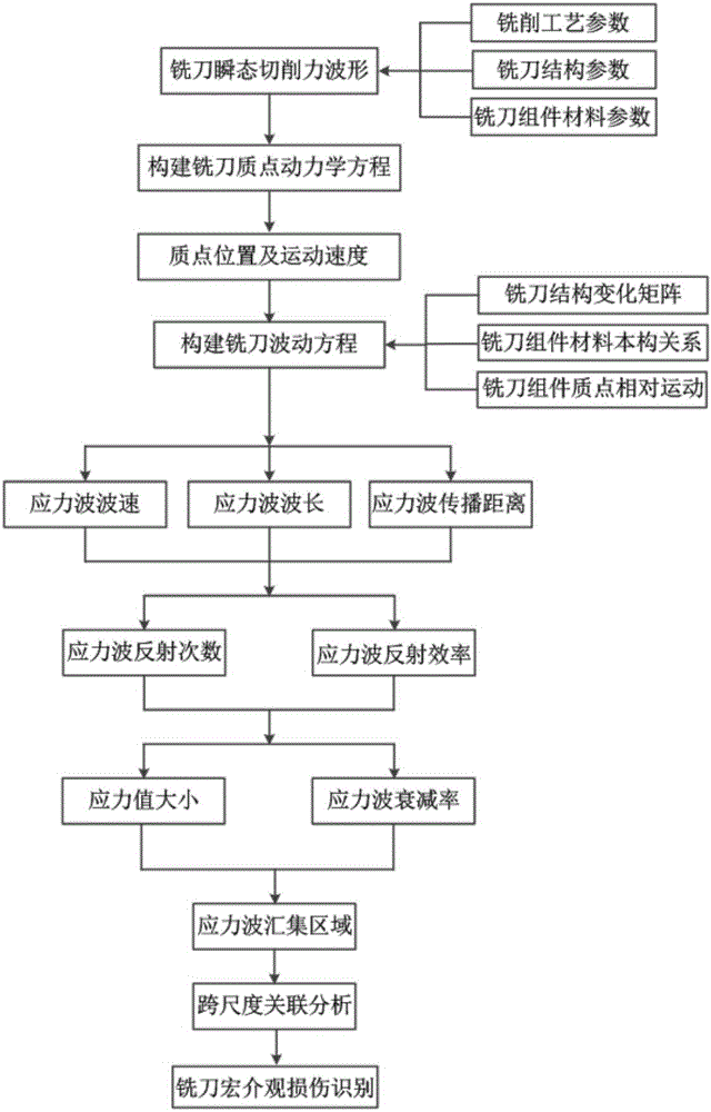
[0074] refer to figure 1 , the high-speed milling cutter wave dynamics damage identification method under the intermittent impact load of the present invention is made of the following steps:

[0075] 1. Establish the transient cutting force model and particle dynamics equation of high-speed milling cutter

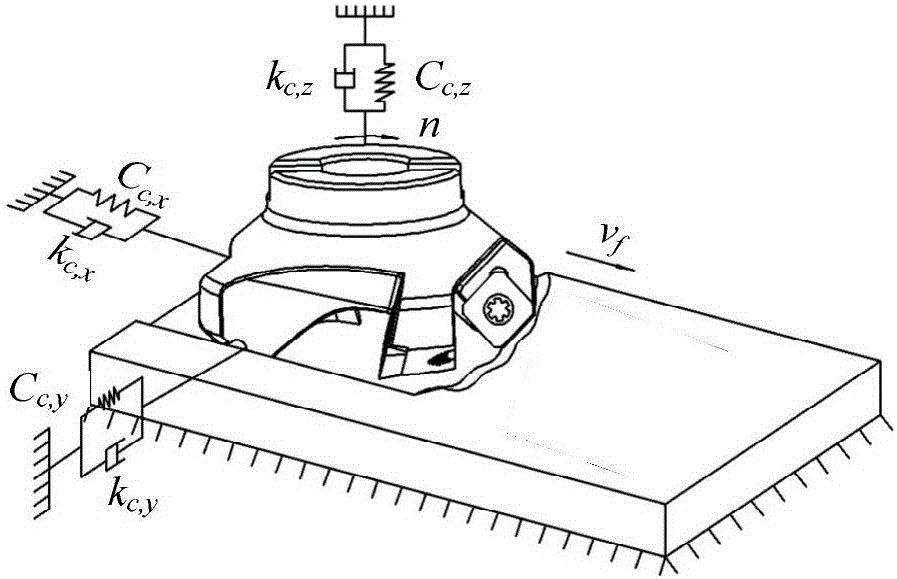
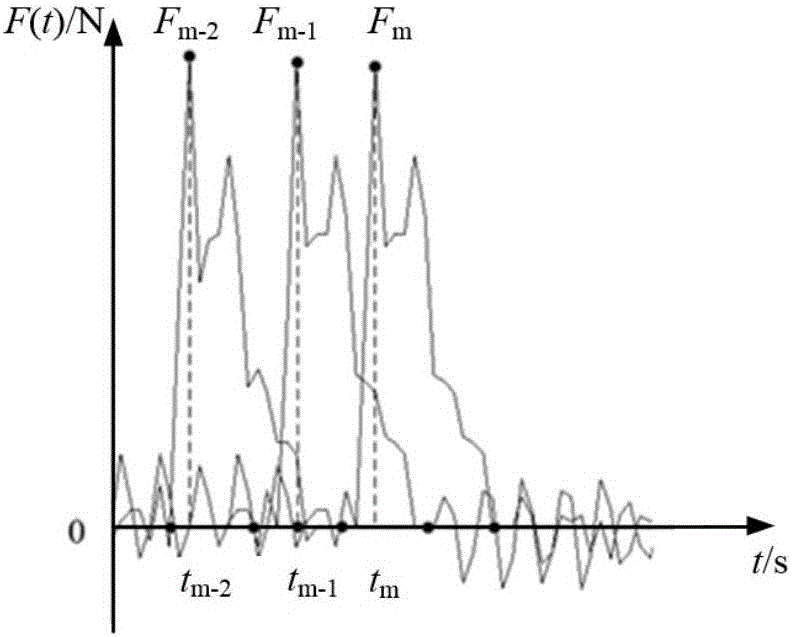
[0076] When the high-speed milling cutter is cutting, due to the intermittent cutting of the cutter teeth and the change of the cutting thickness, the cutting force whose waveform changes periodically becomes one of the main exciting forces that cause the vibration of the tool system. The milling process and transient cutting Force wave like figure 2 , image 3 as shown, figure 2 in, v f is the feed rate of the milling cutter, n is the speed of the milling cutter, k c,x 、k c,y 、k c,z are the modal stiffnesses along the three directions, resp...


PUM


Abstract

The invention discloses a method for identifying wave mechanical damage of a high-speed milling cutter under the intermittent impact load effect. The method is technically characterized by comprising steps as follows: I, a transient cutting force model and an equation of particle dynamics of the high-speed milling cutter are established; II, a wave equation of a stress wave of the high-speed milling cutter is established; III, an attenuating stress value and an attenuation rate of the stress wave of the high-speed milling cutter are solved; IV, the wave mechanical damage of the high-speed milling cutter is identified. With the method, the internal relation of macroscopic and mesoscopic structure domains of the high-speed milling cutter can be disclosed, local macroscopic and mesoscopic damage of the milling cutter is identified, a high-frequency stress wave collecting area of the high-speed milling cutter can be determined, trans-scale association analysis can be performed, in combination with molecular dynamic simulation, the part, prone to damage, of the high-speed milling cutter and the type of the damage in the mesoscale can be identified, the problem of identification of potential damage positions and damage types of a milling cutter assembly under the high-speed intermittent impact load effect is solved in an emphasized manner, and meanwhile, the problem of multi-scale evolution of the wave mechanical damage of the high-speed milling cutter is also solved.

Description

Technical field: [0001] The invention relates to a damage identification method of a high-speed milling cutter, in particular to a wave dynamics damage recognition method of a high-speed milling cutter under the action of an intermittent impact load. Background technique: [0002] Under the condition of high-speed and intermittent cutting, with the change of milling cutter structure, material and cutting parameters, the energy and mass distribution inside the milling cutter will also change. While obtaining high cutting efficiency, the distribution of milling cutter stress field The inhomogeneity increases significantly, and its internal energy continues to accumulate. Under this condition, once the milling cutter is damaged or has potential defects, the degree of damage will develop rapidly. If it cannot be found in time, most of the serious accidents that cannot be repaired will occur. [0003] In the research on the safety of high-speed milling cutters, it was found that...

Claims


Application Information

Patent Timeline
IPC IPC(8): B23Q17/09
CPCB23Q17/0957B23Q2717/006
Inventor 姜彬何田田张明慧
Owner HARBIN UNIV OF SCI & TECH
Learn More