Ripple elimination circuit and led control circuit

A ripple elimination and circuit technology, applied in the field of power electronics, can solve problems such as inability to input current response, achieve fast system response and improve response speed

Active Publication Date: 2017-12-19
JOULWATT TECH ZHANGJIAGANG INC LTD
View PDF5 Cites 0 Cited by
  • Summary
  • Abstract
  • Description
  • Claims
  • Application Information

AI Technical Summary

Problems solved by technology

[0004] In view of this, the object of the present invention is to provide a ripple elimination circuit and LED control circuit capable of fast response to solve the technical problem existing in the prior art that it cannot respond to the input current in time

Method used


Image

  • Ripple elimination circuit and led control circuit
  • Ripple elimination circuit and led control circuit
  • Ripple elimination circuit and led control circuit

Examples


Embodiment Construction

[0036]Preferred embodiments of the present invention will be described in detail below with reference to the accompanying drawings, but the present invention is not limited to these embodiments. The present invention covers any alternatives, modifications, equivalent methods and schemes made within the spirit and scope of the present invention.

[0037] In order to provide the public with a thorough understanding of the present invention, specific details are set forth in the following preferred embodiments of the present invention, but those skilled in the art can fully understand the present invention without the description of these details.

[0038] In the following paragraphs the invention is described more specifically by way of example with reference to the accompanying drawings. It should be noted that all the drawings are in simplified form and use inaccurate scales, which are only used to facilitate and clearly assist the purpose of illustrating the embodiments of th...


PUM


Abstract

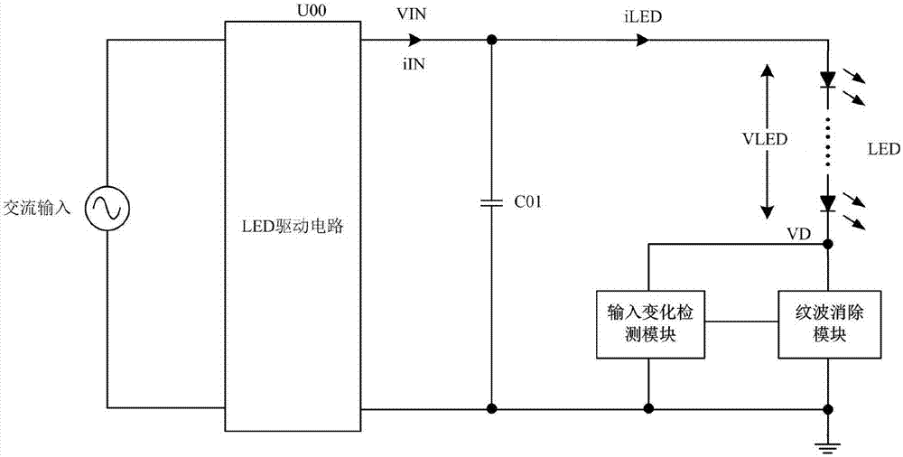
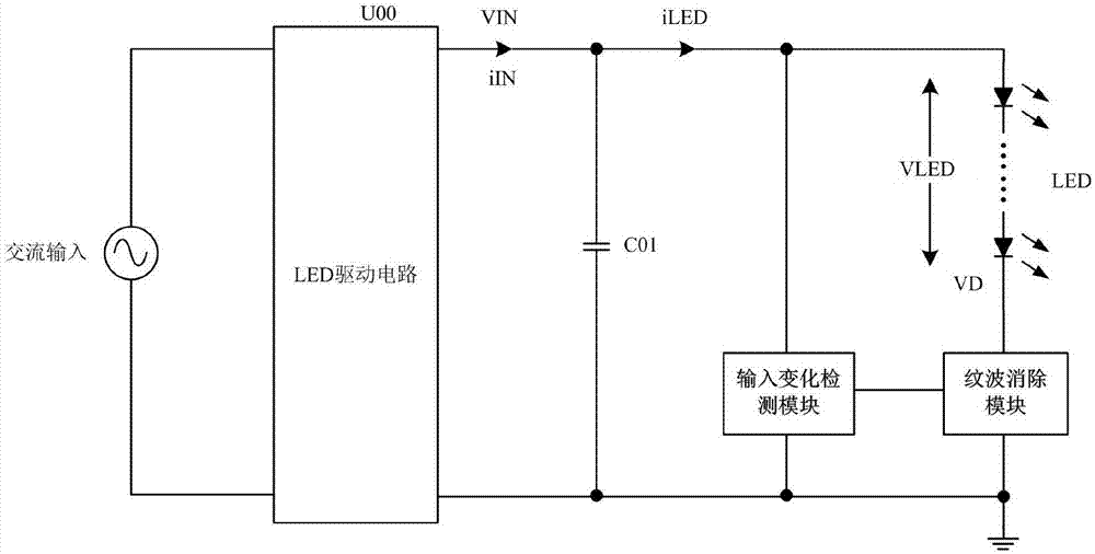
The invention discloses a ripple elimination circuit and an LED control circuit. The LED drive circuit receives an AC input, converts it into a DC power with ripple, and supplies power to an LED load, and the DC power with ripple is connected to the LED load. On the positive side, when the input current increases rapidly, the input change detection module will generate a pull-up current based on the feedback of the signal to be detected that can characterize the input current change, and act on the ripple elimination module through the output end of the input change detection module. The change of the voltage on the capacitive element in the ripple cancellation module improves the response speed of the ripple cancellation circuit, so that the load current can quickly keep up with the change of the input current, so that the system can reach the steady state faster, the system response is fast, and the The LED light will flash.

Description

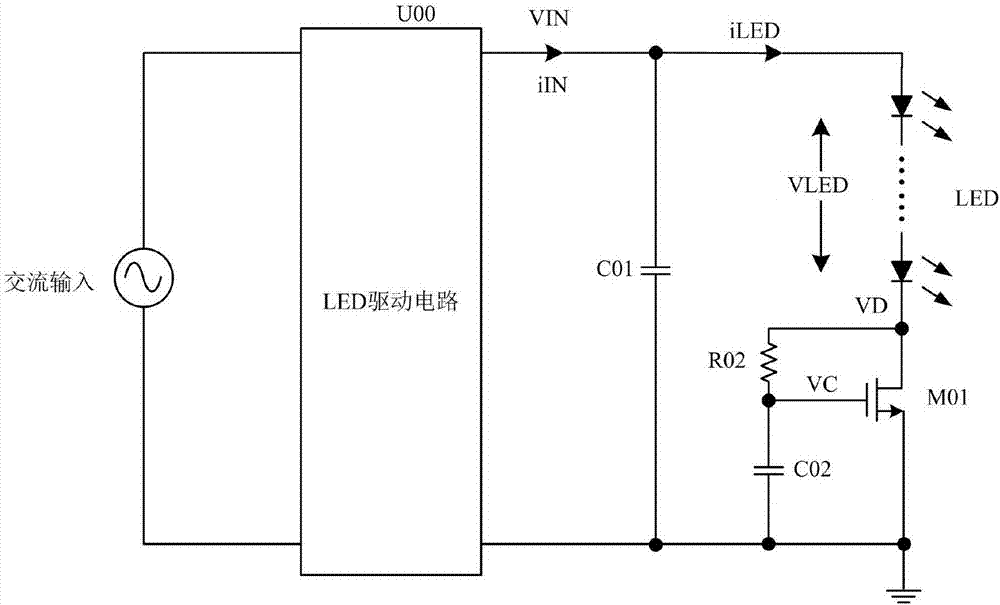
technical field [0001] The invention relates to the technical field of power electronics, in particular to a ripple elimination circuit and an LED control circuit. Background technique [0002] In some applications, the current and voltage ripple will affect the operation of the circuit and the load, and it is often necessary to eliminate the ripple, especially in the LED control circuit. Such as figure 1 As shown in FIG. 2 , an LED control circuit including a ripple cancellation circuit in the prior art is illustrated. The AC input voltage is passed through the LED drive circuit U00 to obtain the voltage VIN, the voltage VIN and the ground are connected to the LED load and the linear adjustment tube M01, the parallel capacitor C01 is connected between the positive pole of the LED load and the ground, the drain of the LED load negative pole wiring adjustment tube M01, and the LED The resistor R02 is connected between the negative electrode of the load and the grid of the l...

Claims


Application Information

Patent Timeline
Patent Type & Authority Patents(China)
IPC IPC(8): H05B33/08H05B44/00
CPCH05B45/44
Inventor 白浪黄必亮任远程周逊伟
Owner JOULWATT TECH ZHANGJIAGANG INC LTD
Why Eureka
Try Eureka