
A detection and analysis method and system for a DC micro-motor product

An analysis method and micro-motor technology, applied in the measurement of current/voltage, measurement device, measurement of electrical variables, etc., can solve the problems of high labor intensity, low production efficiency, inaccurate results, etc., to improve the level of automation and realize automatic Adjust and ensure the effect of accuracy

Active Publication Date: 2019-04-23
曲靖乐天科技有限责任公司
View PDF6 Cites 0 Cited by
  • Summary
  • Abstract
  • Description
  • Claims
  • Application Information

AI Technical Summary

Problems solved by technology

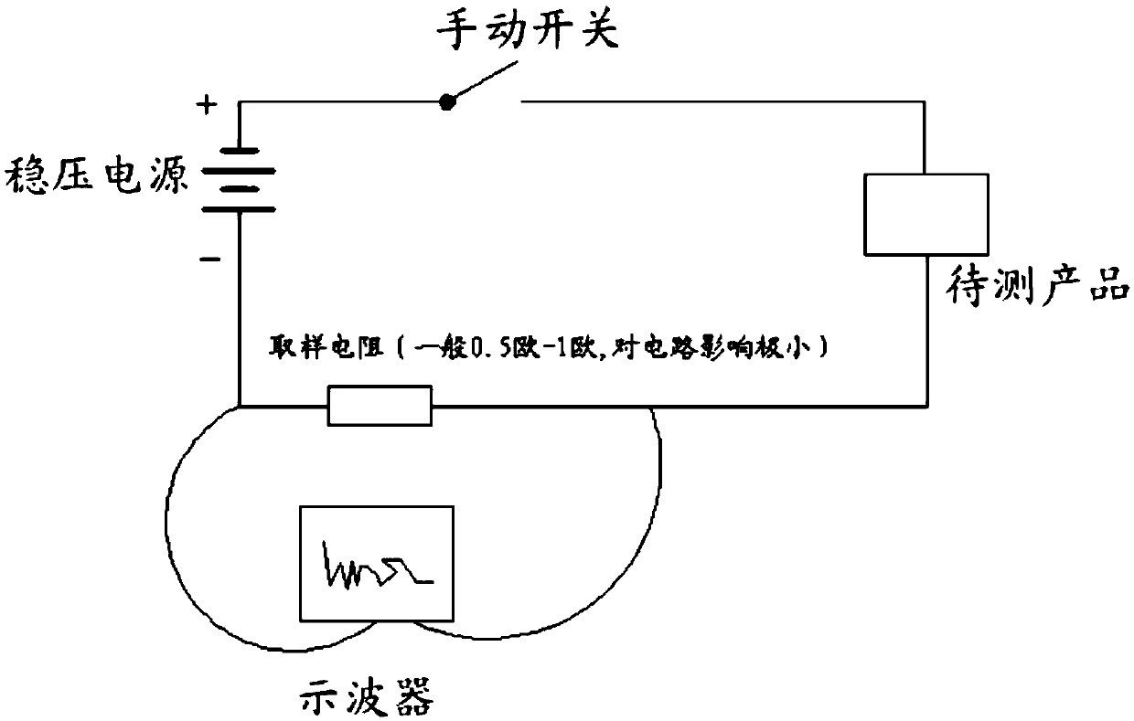
In this method, the inspector uses the knob on the oscilloscope to measure the displayed waveform, which will inevitably cause the problem of inaccurate results
[0005] Because the oscilloscope is a general-purpose device, it can only give the detected current waveform for the testers to analyze by themselves. There is no detection software (program) for different products, and it cannot automatically calculate, analyze, compare, and process.
Due to the need for manual identification, the existing technology can only test one product at a time, the production efficiency is extremely low, and the labor intensity is high
In addition, the existing technology can only realize the traceability of product testing results, which can only be recorded manually on paper or input into a computer. In the case of mass testing, it is very time-consuming to implement

Method used


Image

  • A detection and analysis method and system for a DC micro-motor product
  • A detection and analysis method and system for a DC micro-motor product
  • A detection and analysis method and system for a DC micro-motor product

Examples


Embodiment Construction

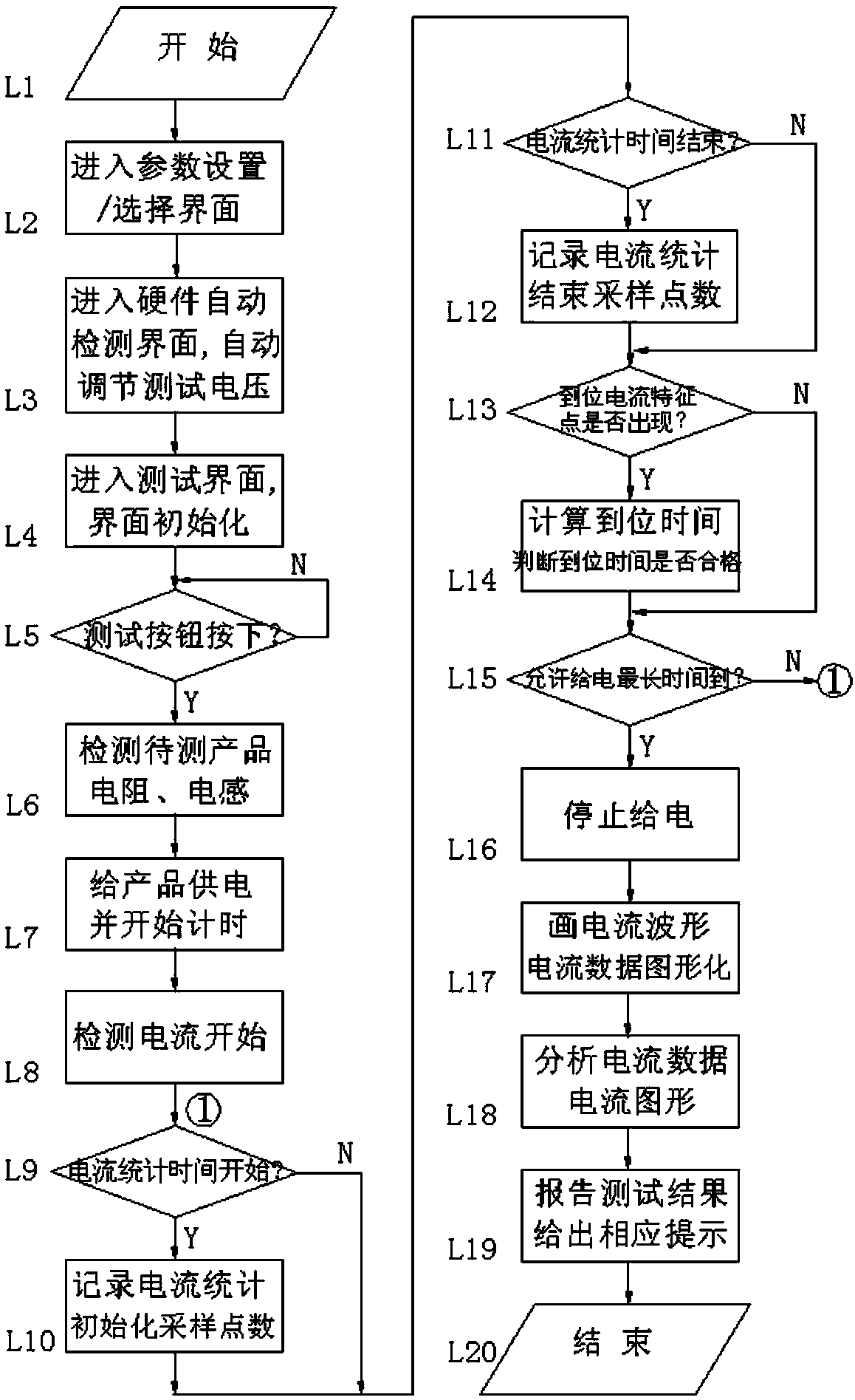
[0079] See figure 1 — Figure 12 , a detection and analysis method for a DC micro-motor product, the steps are as follows:

[0080] L1: start;

[0081] L2: Enter the parameter setting / selection interface;

[0082] L3: Enter the hardware automatic detection interface, automatically adjust the test voltage

[0083] In order to improve the automation of the equipment, the test program can automatically detect the hardware and automatically adjust the test voltage. If the hardware self-test fails, a maintenance message will pop up. After the hardware self-test is normal, it will automatically enter the test interface;

[0084] L4: Enter the test interface, interface initialization

[0085] Initialize the test interface to prepare for the test;

[0086] L5: Test if the button is pressed

[0087] The program waits for the tester to press the test button. After the test button is pressed, the program starts to test the product;

[0088] L6: Detect the resistance and inductance...


PUM


Abstract

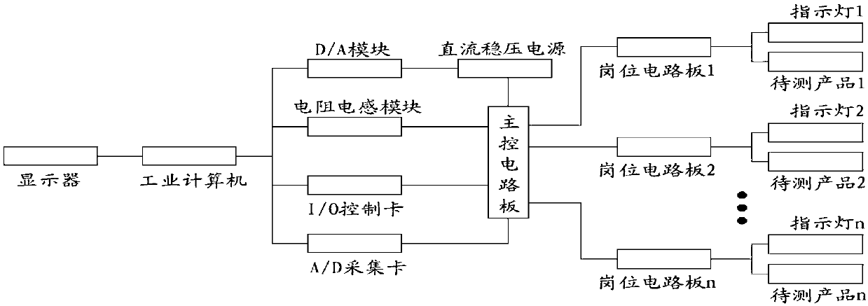
The invention relates to a detection analysis method and a system for DC micro-motor motor, wherein the system comprises an industrial computer, an A / D collection card, an I / O control card, an inductance and resistance, a D / A module, a display, a DC stabilized power supply, a main control circuit board, a position circuit board and a cabinet. The test voltage output and set by DC stabilized power supply can be automatically regulated by the combination method of software and hardware; the production rotation can be automatically controlled, the current data of whole rotation process can be collected effectively; and the current data can be drawn to the current waveform. The current data can be judged whether to be abnormal or not by analyzing the current data of some point or points or current data in some section or some sections, and then the product can be analyzed. The operation time of the product in the stage or some stage or stages can be judged by analyzing the current waveform change, and the current waveform can be judged whether to be abnormal or not so as to analyze the product.

Description

technical field [0001] The invention belongs to the technical field of current detection, and in particular relates to a detection and analysis method and system for DC micro-motor products. Background technique [0002] DC micro-motor products: refer to products driven by DC micro-motors, such as: DC micro-motors, smart motor valves, smart watches, electric toys for children, etc. [0003] Traditional method 1: use a dry battery and a DC regulated power supply, connect a mechanical ammeter in series, and power on the product to see if the product can operate normally, and check the highest current value. This method of using a mechanical ammeter to detect products can only roughly know the magnitude of the current of the product during operation, and other details cannot be obtained. [0004] Traditional method 2: Use an oscilloscope in series with a resistor to observe the current magnitude and current change when the product is running. The tester needs to measure the cu...

Claims


Application Information

Patent Timeline
Patent Type & Authority Patents(China)
IPC IPC(8): G01R27/26G01R27/02G01R19/25G01R15/00
CPCG01R15/00G01R19/2506G01R19/2509G01R27/02G01R27/26
Inventor 刘冬华杨凤欧阳海彬杨金
Owner 曲靖乐天科技有限责任公司
Learn More