Plastic bottle conveying clamping finger mechanism and operating method thereof

A working method and technology for plastic bottles, which are applied in bottle filling, liquid bottling, packaging and other directions, can solve the problems of high manufacturing cost, difficult hardening treatment, and high cost, and achieve the effects of low cost, convenient manufacturing and processing, and long service life.

Inactive Publication Date: 2017-01-11
南京保立隆包装机械有限公司
View PDF5 Cites 0 Cited by
  • Summary
  • Abstract
  • Description
  • Claims
  • Application Information

AI Technical Summary

Problems solved by technology

[0004] 1. Cam clamping type: such as Figure 7 , characterized by simple structure; the disadvantage is that the cam and spring wear too fast
[0005] 2. Connecting rod clamping type, such as Figure 8 , the advantages of this kind of clamp finger are long service life and large clamping force; the disadvantages are complex structure, large number of parts and high manufacturing cost
[0006] 3. Gear synchronous clamping type, such as Figure 9 , the advantage of this kind of clamp finger is that it is simple in structure and easy to clean; the disadvantage is that the tooth surface needs to be hardened
If the tooth surface is not hardened, it is easy to wear; if it is hardened, since the finger material is usually made of austenitic stainless steel (requires corrosion resistance), surface hardening is difficult and costly

Method used


Image

  • Plastic bottle conveying clamping finger mechanism and operating method thereof
  • Plastic bottle conveying clamping finger mechanism and operating method thereof
  • Plastic bottle conveying clamping finger mechanism and operating method thereof

Examples


Embodiment Construction

[0032] The present invention will be further described below in conjunction with accompanying drawing.

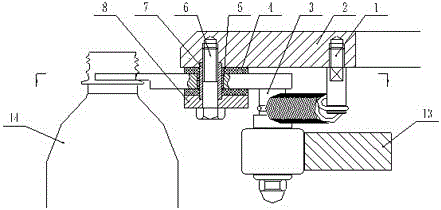
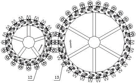
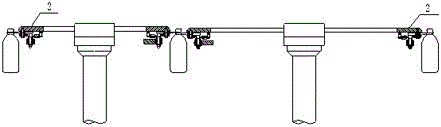
[0033] The plastic bottle conveying finger mechanism provided by the present invention is as figure 1 As shown, it includes a number of star wheel discs 2 and a number of fingers installed on the circumference of the star wheel disc 2, and each star wheel disc 2 is fixed with a number of positioning sleeves 7, and the fingers include driven fingers 9 and active The clamp finger 10, the driven clamp finger 9 and the active clamp finger 10 are connected to the positioning sleeve 7 through the sliding bearing 5 and rotate around the positioning sleeve 7, and the driven clamp finger 9 and the active clamp finger 10 are connected by a transmission pin 18; The tail end of the active clamp finger 10 is connected with a pressing roller 12 through the roller shaft 3, and the star wheel disc 2 is fixed with a tension spring hanging column 1, and a clamping tension spring 11 is conne...


PUM


Abstract

The invention provides a plastic bottle conveying clamping finger mechanism and an operating method thereof. The plastic bottle conveying clamping finger mechanism comprises a plurality of star wheel discs and a plurality of clamping fingers installed on the circumferences of the star wheel discs, wherein when the plastic bottle conveying clamping fingers need clamping, clamping tension springs pull roller shafts, so that driving clamping fingers rotate clockwise, and meanwhile, driven clamping fingers are driven by drive pins to rotate counterclockwise, and thus the plastic bottle conveying clamping fingers are closed; when the plastic bottle conveying clamping fingers need opening, expansion cams press rollers, so that the roller shafts overcome the tension of the clamping tension springs, thus the driving clamping fingers rotate counterclockwise, and meanwhile, the driven clamping fingers are driven by the drive pins to rotate clockwise, and then the plastic bottle conveying clamping fingers are opened. The plastic bottle conveying clamping finger mechanism provided by the invention is long in service life, is safe and reliable, has a hygienic structure, does not have cleaning dead space, is convenient to manufacture and is low in cost.

Description

technical field [0001] The invention relates to the field of plastic bottle conveying devices, in particular to a plastic bottle conveying finger mechanism and a working method thereof, which are applied to cleaning, sterilizing, filling and sealing equipment of plastic bottles. Background technique [0002] On the cleaning, sterilization, filling and sealing equipment of plastic bottles, the transfer of bottles is generally carried out by clamping the neck of the bottle, and the clamping finger for clamping the bottle is an essential part. [0003] At present, there are clamp fingers, mainly in the following forms: [0004] 1. Cam clamping type: such as Figure 7 , characterized by simple structure; the disadvantage is that the cam and spring wear too fast. [0005] 2. Connecting rod clamping type, such as Figure 8 , The advantages of this kind of clamp finger are long service life and large clamping force; the disadvantages are complex structure, large number of parts, ...

Claims


Application Information

Patent Timeline
IPC IPC(8): B67C3/24
CPCB67C3/24
Inventor 陈小平黄东宁
Owner 南京保立隆包装机械有限公司
Why Eureka
Try Eureka