Limiting switch of lifting machine

A technology of limit switch and elevator, which is applied in the direction of lifting frame, lifting device, safety device of lifting equipment, etc., can solve the problems such as the inability to meet the work requirements and the inability of the contact head to contact the conflicting parts, and achieves easy production and manufacturing. Simple and structurally stable effect

Inactive Publication Date: 2017-01-11
苏州威尔特铝合金升降机械有限公司
View PDF5 Cites 0 Cited by
  • Summary
  • Abstract
  • Description
  • Claims
  • Application Information

AI Technical Summary

Problems solved by technology

[0002] Limit switches are very common in daily life. For example, limit switches used in elevators basically include a base arranged on the elevator frame, a rotating member rotatably arranged on the base, and a rotating member for making the rotating member The torsion spring that can restore the initial state by itself, the contact bar fixed on the rotating part, and the contact head set at one end of the contact bar. When the elevator is rising and falling, the lifting rod contacts the contact head until it is lifted and separated from the contact head. Contact, which shows that the lifting process of the elevator is stable and safe. However, the position of the contact bar of the above-mentioned limit switch is fixed. Once the contact part of the lifting rod changes, the contact head will not be able to contact with the contact part. At this time, the limit switch switch, will not be able to meet the job requirements

Method used


Image

  • Limiting switch of lifting machine
  • Limiting switch of lifting machine

Examples


Embodiment Construction

[0011] The preferred embodiments of the present invention are given below in conjunction with the accompanying drawings to describe the technical solution of the present invention in detail.

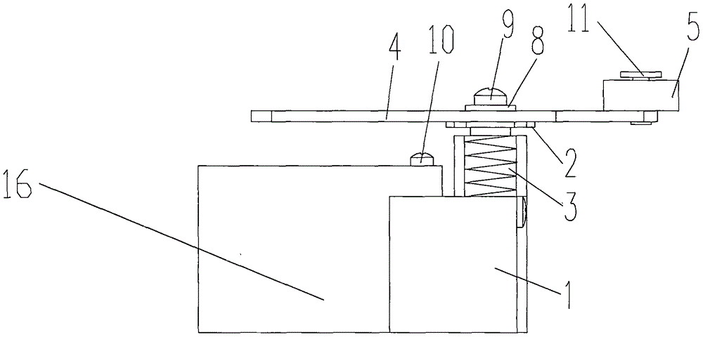
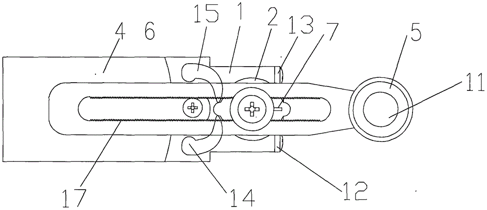
[0012] Such as Figure 1 to Figure 2 As shown, the limit switch of the elevator of the present invention includes a base 1, a rotating member 2, a torsion spring 3, a contact strip 4, a contact head 5, a long slot 6, a locking member 7, a gasket 8, a large cross bolt 9, Small cross bolt 10, elastic buckle 11, left limit signal lamp 12, right limit signal lamp 13, left limit slider 14, right limit slider 15, elevator boundary frame 16, anti-skid sawtooth 17, base 17 through small No. cross bolt 10 is fixed on the boundary frame 16 of the elevator. The boundary frame 16 of the elevator is located on the side of the base 1. The side of the base 1 is provided with a left limit signal lamp 12 and a right limit signal lamp 13. The upper end of the base 1 passes through the torsion spring 3 and...


PUM


Abstract

The invention discloses a limiting switch of a lifting machine. The limiting switch comprises a base and the like. The base is fixed to a boundary frame of the lifting machine through a small cross-shaped bolt. A left limiting signal lamp and a right limiting signal lamp are arranged on the side edge of the base. The upper end of the base is connected with a rotation piece through a torsion spring. A contact strip is fixed to the rotation piece through a large cross-shaped bolt. A gasket is arranged between the large cross-shaped bolt and the contact strip. A contact head is arranged at the front end of the contact strip and fixed to the contact strip through an elastic buckle. A long-strip-shaped through groove is formed in the contact strip, a left limiting sliding block and a right limiting sliding block are arranged on the two sides of the contact strip, and a locking piece is arranged at the upper end of the rotation piece. By means of the limiting switch, the limiting condition of the strip can be adjusted, the limiting requirements of different brands and types of lifting machines under different work conditions are met, the structure is simple and stable, and producing and manufacturing are easy.

Description

technical field [0001] The invention relates to a limit switch, in particular to a limit switch of an elevator. Background technique [0002] Limit switches are very common in daily life. For example, limit switches used in elevators basically include a base arranged on the elevator frame, a rotating member rotatably arranged on the base, and a rotating member for making the rotating member The torsion spring that can restore the initial state by itself, the contact bar fixed on the rotating part, and the contact head set at one end of the contact bar. When the elevator is rising and falling, the lifting rod contacts the contact head until it is lifted and separated from the contact head. Contact, which shows that the lifting process of the elevator is stable and safe. However, the position of the contact bar of the above-mentioned limit switch is fixed. Once the contact part of the lifting rod changes, the contact head will not be able to contact with the contact part. At t...

Claims


Application Information

Patent Timeline
Patent Type & Authority Applications(China)
IPC IPC(8): B66F7/06B66F7/28B66F17/00
CPCB66F7/06B66F7/28B66F17/00
Inventor 杨光耀
Owner 苏州威尔特铝合金升降机械有限公司
Why Eureka
Try Eureka