
Built-in material pushing mechanism for box packing machine

A push mechanism and built-in technology, applied in the field of mechanisms that can push packaging materials, can solve problems such as being unfavorable for material packing and maintenance, increasing packaging costs and manpower and material resources, and affecting the sight of operators. Small footprint, high degree of automation, and reasonable placement

Inactive Publication Date: 2017-01-11
林佳一
View PDF10 Cites 0 Cited by
  • Summary
  • Abstract
  • Description
  • Claims
  • Application Information

AI Technical Summary

Problems solved by technology

The packaging box is sideways tipping type, and the medicine board materials and instructions are horizontal push type and front position (meaning that the push mechanism is in front of the frame and packaging materials), which occupies a lot of useful space of the cartoning machine and affects the operator The working line of sight is not conducive to the packaging and maintenance of materials into the box, which increases the packaging cost and manpower and material resources, and the work efficiency is also low

Method used


Image

  • Built-in material pushing mechanism for box packing machine
  • Built-in material pushing mechanism for box packing machine

Examples


Embodiment Construction

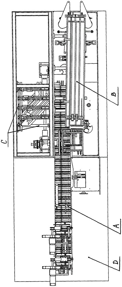
[0009] refer to figure 1 , figure 2 It can be seen that the built-in material push mechanism C of the cartoning machine of the present invention includes a pusher frame 17, a left pusher transmission assembly 18, a right pusher transmission assembly 19, and the left pusher transmission assembly 18, the right pusher transmission assembly 19 is contained in the inside (also can be referred to as built-in) of pushing material frame 17, on described pushing material frame 17, and between left pushing material transmission assembly 18 and right pushing material transmission assembly 19 places are respectively equipped with Straight track 8, first curved track 6, second curved track 13, in the straight track 8 (horizontal type), first curved track 6 (curved type), second curved track Some groups of push rods 9 are housed on the rail 13 (curved type), a push head 16 is housed on one end of the push rod 9, and a push slider 12 is housed on its other end (having upper and lower parts...


PUM


Abstract

The invention discloses a built-in material pushing mechanism for a box packing machine. A left material pushing driving component and a right material pushing driving component of the built-in material pushing mechanism are arranged inside a material pushing rack; a linear track, a first curved track and a second curved track are arranged at a position between the left material pushing driving component and the right material pushing driving component on the material pushing rack; a plurality of groups of material pushing rods are respectively arranged on the linear track, the first curved track and the second curved track; and a main rotary gear, a specification transmitting chain wheel, a chain transmitting plate chain wheel and a chain transmitting plate adjusting chain wheel are sequentially arranged at the end part of a material feeding rotating shaft of the left material pushing driving component from outside to inside. According to the built-in material pushing mechanism disclosed by the invention, materials and a specification thereof are quickly, conveniently, accurately and effectively fed into the packing box. The built-in material pushing mechanism is small in occupied space, reasonable in placement, and convenient to maintain and operate. Therefore, a work vision of operations is widened. The built-in material pushing mechanism has the advantages of high working efficiency, good stability, convenience and effectiveness in operation, high degree of automation and cost conservation.

Description

technical field [0001] The invention relates to a packaging machine, in particular to a mechanism for pushing packaging materials (including instructions) applied to a cartoning machine. Background technique [0002] At present, the cartoning machine is an automatic boxing and packaging equipment suitable for medicine boards, packaging bags (granules), cosmetics, food, health products or similar materials. Its working process is the push of medicine boards or similar materials and the delivery of instructions. , the delivery of the packaging box, the material pushing into the packaging box, the closing and sending out and other processes. The packaging box is sideways tipping type, and the medicine board materials and instructions are horizontal push type and front position (meaning that the push mechanism is in front of the frame and packaging materials), which occupies a lot of useful space of the cartoning machine and affects the operator The working line of sight is not...

Claims


Application Information

Patent Timeline
Patent Type & Authority Applications(China)
IPC IPC(8): B65B35/20B65B61/20
CPCB65B35/20B65B61/20
Inventor 林佳一
Owner 林佳一
Learn More