Gantry type annular container winding machine

A winding machine and gantry-type technology, which is applied in the production field of fiber winding products in annular containers, can solve the problems of grinding yarn and inaccurate positioning, and achieve the effects of high winding precision, precise control of the position of the wire nozzle, and simple operation

Inactive Publication Date: 2017-01-11
XIAN AEROSPACE COMPOSITE MATERIALS INST
View PDF4 Cites 6 Cited by
  • Summary
  • Abstract
  • Description
  • Claims
  • Application Information

AI Technical Summary

Problems solved by technology

[0004] The purpose of the present invention is to overcome the above-mentioned deficiencies in the prior art, and to provide a gantry-type ring-shaped container winding machine, which uses a mandrel clamping device to ensure that the ring-shaped mandrel is fixed during the winding process of the ring-shaped container, and uses a wire nozzle bracket to The rotating device drives the ring-shaped wire nozzle to make the ring-shaped wire nozzle rotate around the outer side of the ring mandrel. The driving mechanism drives the ring-shaped wire nozzle to make it rotate around the cross-section of the ring mandrel. The two rotations are combined to make the fiber wind on the surface of the mandrel. It solves the problems of inaccurate positioning and yarn grinding caused by the friction transmission mode of the ring mandrel

Method used


Image

  • Gantry type annular container winding machine
  • Gantry type annular container winding machine
  • Gantry type annular container winding machine

Examples


Embodiment Construction

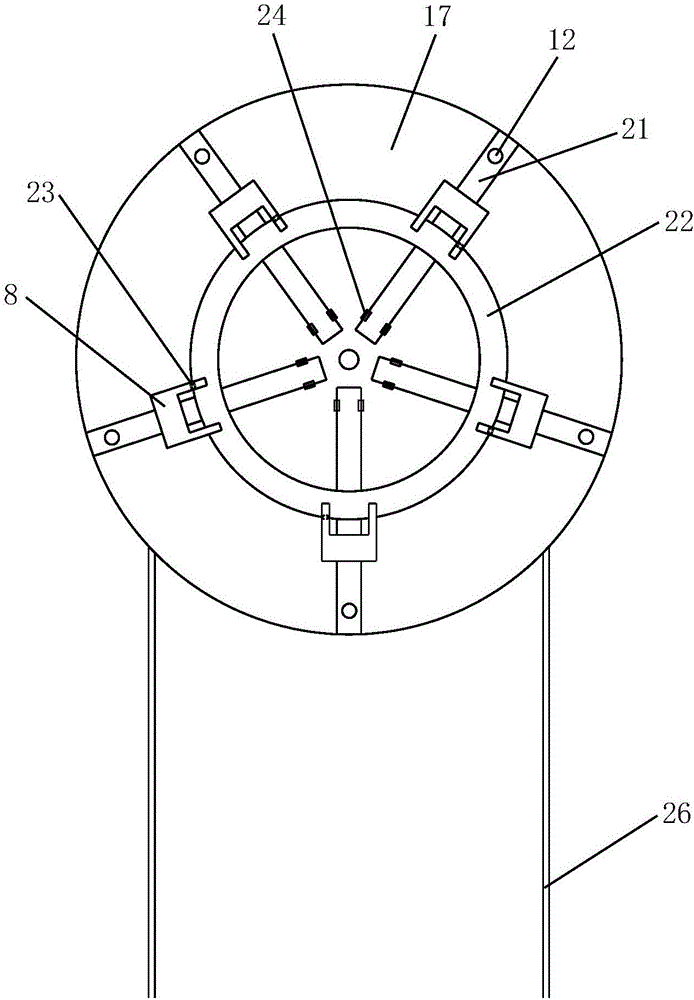
[0036] like figure 1 , image 3 and Figure 4 As shown, the present invention comprises gantry support 1, base 17 and wire mouth support 5, and described base 17 is arranged in gantry support 1, and described silk mouth support 5 is arranged on the top of base 17, and multiple A mandrel clamping device for fixing the annular mandrel 22, the top of the gantry support 1 is equipped with a silk mouth support rotating device for driving the silk mouth support 5 to rotate around the outer circumference of the annular mandrel 22, the silk mouth The support 5 is installed at the bottom of the rotating device of the thread nozzle support, the thread nozzle support 5 is equipped with an annular thread nozzle 6, and the thread nozzle support 5 is equipped with a ring for driving the annular thread nozzle 6 around the annular mandrel 22 cross section A drive mechanism for circumferential rotation, and a yarn guide wheel 7 is installed on the annular yarn nozzle 6 .

[0037] The gantry...


PUM


Abstract

The invention discloses a gantry type annular container winding machine. The gantry type annular container winding machine comprises a gantry bracket, a base and a wire nozzle bracket, wherein the base is arranged in the gantry bracket, the wire nozzle bracket is arranged above the base, a plurality of core mold clamping devices for fixing an annular core mold are mounted on the base, a wire nozzle bracket rotating device for driving the wire nozzle bracket to rotate around the periphery of the outer side of the annular core mold is mounted on the top of the gantry bracket, the wire nozzle bracket is mounted in the bottom of the wire nozzle bracket rotating device, an annular wire nozzle is mounted on the wire nozzle bracket, a driving mechanism for driving the annular wire nozzle to rotate around the periphery of the cross section of the annular core mold, and yarn guiding wheels are mounted on the annular wire nozzle. According to the gantry type annular container winding machine disclosed by the invention, the annular core mold is immobilized by virtue of the core mold clamping devices, the annular wire nozzle rotates around the periphery of the outer side of the annular core mold and around the periphery of the cross section of the annular core mold, and a fiber is wound on the surface of the core mold by rotational synthesis, so that the problem of inaccurate locating and yarn grinding caused by a friction drive mode of the annular core mold is solved.

Description

technical field [0001] The invention belongs to the technical field of production of annular container fiber winding products, and in particular relates to a gantry type annular container winding machine. Background technique [0002] In aviation, aerospace and military fields, due to its special application occasions, ring-shaped high-pressure vessels need to be widely used. At present, these ring-shaped containers are all metal containers, which are heavy in weight and easily produce lethal fragments when they are destroyed, so they are limited in practical application. The use of annular container fiber winding products can well solve the shortcomings of metal containers, but due to the structural characteristics of the annular container itself, it is very difficult to manufacture annular container winding equipment with good performance, and the manual method has low production efficiency and product quality. Difficult to guarantee and other shortcomings. [0003] The ...

Claims


Application Information

Patent Timeline
Patent Type & Authority Applications(China)
IPC IPC(8): B29C53/64B29C53/80B29L31/00
CPCB29C53/64B29C53/8008B29L2031/712
Inventor 顾涛王健杨杰耿争言索红霞杜兰兰
Owner XIAN AEROSPACE COMPOSITE MATERIALS INST
Why Eureka
Try Eureka