
A High Power and High Efficiency Doherty Power Amplifier

A power amplifier, high-efficiency technology, applied in the field of radio frequency communication, can solve the problems such as the maximum saturation efficiency and back-off efficiency of Doherty power amplifier cannot be further improved, the improvement of harmonic control efficiency is not considered, and the overall area of ​​the power amplifier is increased. The effect of high linearity, improved efficiency, and increased saturated output power

Active Publication Date: 2019-01-04
HANGZHOU DIANZI UNIV
View PDF2 Cites 0 Cited by
  • Summary
  • Abstract
  • Description
  • Claims
  • Application Information

AI Technical Summary

Problems solved by technology

However, the peak power amplifier of the traditional Doherty power amplifier only contains one power amplifier, so the power contributed by the peak power amplifier in the entire Doherty is greatly restricted. large, but this parallel structure will lead to an increase in the overall area of ​​the power amplifier; in addition, in the Doherty power amplifier in the prior art, the carrier power amplifier is biased in the AB class operation mode, and the peak power amplifier is biased in the C class operation mode. Due to the traditional AB Class and Class C power amplifiers, resulting in the maximum saturation efficiency and fallback efficiency of Doherty power amplifiers cannot be further improved
At the same time, the current carrier power amplifier and peak power amplifier in the Doherty power amplifier only consider the fundamental wave matching and do not consider the improvement of the efficiency of the harmonic control. The focus of Doherty's research is how to improve the back-off efficiency and saturation output of the power amplifier. power

Method used


Image

  • A High Power and High Efficiency Doherty Power Amplifier
  • A High Power and High Efficiency Doherty Power Amplifier

Examples


Embodiment Construction

[0024] The following are specific embodiments of the present invention and in conjunction with the accompanying drawings, the technical solutions of the present invention are further described, but the present invention is not limited to these embodiments.

[0025] Aiming at the defects existing in the prior art, the applicant conducted in-depth research on the structure of the Doherty power amplifier in the prior art, and the applicant found that the peak power amplifier in the Doherty power amplifier in the prior art adopts a single-stage power amplifier, so that the peak power amplifier in the entire Doherty At the same time, the carrier power amplifier is biased in class AB working mode, and the peak power amplifier is set in class C working mode, and only the influence of fundamental wave matching on the efficiency output power is considered.

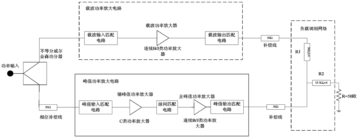
[0026] see figure 1 , shows the structural block diagram of high-power high-efficiency Doherty power amplifier of the present inv...


PUM


Abstract

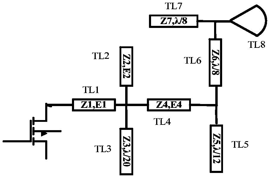
The invention provides a high-power and high-efficiency Doherty power amplifier, which includes an unequal Wilkinson power divider, a carrier power amplifier circuit, a peak power amplifier circuit and a load modulation network, and the carrier power amplifier circuit adopts a continuous B / J class power amplifier , The peak power amplifying circuit adopts a two-stage power amplifier cascade structure, the auxiliary peak power amplifying circuit adopts a class C power amplifier, and the main peak power amplifying circuit adopts a continuous B / J class power amplifier. Compared with the prior art, the present invention adopts a new Doherty structure, which can greatly improve the saturated output power while ensuring the efficiency. The auxiliary peak power amplifier adopts ordinary class C, and the main peak power amplifier and carrier power amplifier adopt continuous B / J class. Using its harmonic control network can well control the second and fourth short circuits, and the third and fifth open circuits, so that the output of the power amplifier The current waveform is approximately a half sine wave, and the voltage waveform is approximately a square wave, which greatly improves Doherty's back-off efficiency and saturated output power.

Description

technical field [0001] The invention relates to the technical field of radio frequency communication, in particular to a Doherty power amplifier with high power and high efficiency. Background technique [0002] In recent years, wireless communication technology has been greatly developed, and the modulation methods are becoming more and more complex. The power amplifier, as the final module in the transmitter, is the component with the largest power consumption in the entire radio frequency system. Its main function is to amplify the power of the signal output by the previous stage, and then send the amplified signal to the antenna for transmission. Due to the change of the transmission mechanism and the increase of the transmission distance, the ability of the power amplifier to output high enough power and have a high enough efficiency has become the main technical index pursued at present, and the linearity is also a key index of the power amplifier. This is mainly refl...

Claims


Application Information

Patent Timeline
Patent Type & Authority Patents(China)
IPC IPC(8): H03F1/02H03F1/32H03F3/195H03F3/213
CPCH03F1/0288H03F1/32H03F3/195H03F3/213
Inventor 程知群轩雪飞刘国华李江舟张明赵子明涂琴
Owner HANGZHOU DIANZI UNIV
Learn More