
Drive control circuit, drive control method and drive control system for AC-DC (Alternating Current-Direct Current) circuit

A technology for driving control circuits and circuits, applied in electrical components, output power conversion devices, AC power input conversion to DC power output, etc., can solve the problems of limited PFC effect, input current is not sinusoidal, etc. Improve the sine degree and reduce the effect of THD

Active Publication Date: 2017-01-04
JOULWATT TECH INC LTD
View PDF7 Cites 6 Cited by
  • Summary
  • Abstract
  • Description
  • Claims
  • Application Information

AI Technical Summary

Problems solved by technology

Although this method does not need to sample the input grid voltage, but the input current is not sinusoidal, the effect of PFC is limited and needs to be optimized

Method used


Image

  • Drive control circuit, drive control method and drive control system for AC-DC (Alternating Current-Direct Current) circuit
  • Drive control circuit, drive control method and drive control system for AC-DC (Alternating Current-Direct Current) circuit
  • Drive control circuit, drive control method and drive control system for AC-DC (Alternating Current-Direct Current) circuit

Examples


Embodiment Construction

[0038] In order to make the above objects, features and advantages of the present invention more comprehensible, specific implementations of the present invention will be described in detail below in conjunction with the accompanying drawings.

[0039] In the following description, numerous specific details are set forth in order to provide a thorough understanding of the present invention. However, the present invention can be implemented in many other ways different from those described here, and those skilled in the art can make similar extensions without violating the connotation of the present invention, so the present invention is not limited by the specific implementations disclosed below.

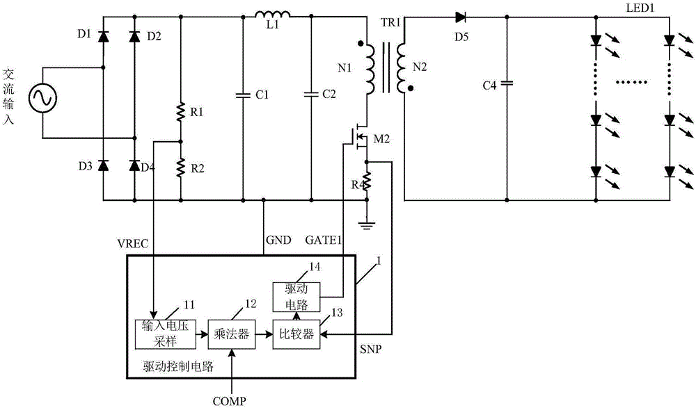
[0040] see Figure 4 , the driving control circuit of the AC-DC circuit in the embodiment of the present invention includes: a driving circuit 33 , a sample and hold circuit 31 and a charge control circuit 32 . AC-DC circuits can be as figure 1 The flyback circuit (FLYBACK) can al...


PUM


Abstract

The invention provides a drive control circuit, a drive control method and a drive control system for an AC-DC (Alternating Current-Direct Current) circuit. The driving control circuit comprises a drive circuit, a sample hold circuit and a charge control circuit, wherein the output end of the drive circuit is connected with the control end of an AC-DC circuit switch tube so as to drive on and off of the switch tube; the sample hold circuit is used for receiving a current sampling signal of the AC-DC circuit switch tube, performing sample hold on the current sampling signal according to a compensation signal in a conduction zone of the switch tube during each switching period, and generating and outputting a sample hold signal; the charge control circuit is connected with the sample hold circuit and the drive circuit, and is used for receiving the sample hold signal and the current sampling signal, positively regulating charges according to the sample hold signal, and negatively regulating charges according to the current sampling signal of the conduction zone, and a comparison result of an obtained charge value signal and a preset value is used for controlling the drive circuit to shut off the switch tube. An input voltage does not need to be additionally or separately sampled, a sine signal of which input current has the same phase with input voltage can be realized, and high PF can be obtained.

Description

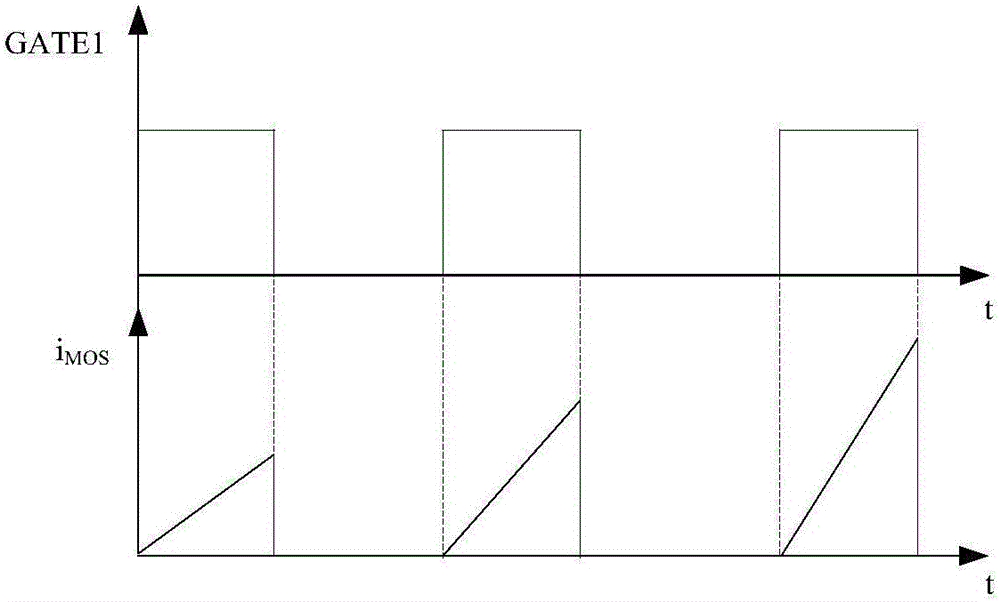
technical field [0001] The invention relates to switching power supply technology, in particular to a drive control circuit, method and system for an AC-DC circuit. Background technique [0002] In the AC / DC (alternating current / direct current) conversion circuit, in order to reduce the pollution of the circuit to the grid, the input current waveform needs to be sinusoidal and in phase with the grid voltage. That is to say, low THD (Total Harmonic Distortion, total harmonic distortion) and high power factor (PF) are required. Such a high PF circuit is called a circuit with power factor correction (PFC). [0003] Such as figure 1 The flyback circuit shown is a commonly used PFC circuit, and the flyback circuit includes: a rectifier bridge constructed by diodes D1-D4, an inductor L1, a transformer TR1, a switch tube M2 (for example, a MOS tube), and a sampling resistor R4 , diode D5, load LED1, etc. The input terminal of the rectifier bridge receives the AC input signal, t...

Claims


Application Information

Patent Timeline
Patent Type & Authority Applications(China)
IPC IPC(8): H02M1/08H02M7/217H02M1/00
CPCH02M1/00H02M1/08H02M7/217H02M1/0003
Inventor 黄必亮胡长伟任远程周逊伟
Owner JOULWATT TECH INC LTD
Learn More