
Pore imaging method and device based on spatial domain phase correction

A technology of phase correction and imaging method, which is applied in the direction of measuring devices, instruments, scientific instruments, etc., and can solve the problems of limited imaging resolution, instability, and low signal-to-noise ratio

Active Publication Date: 2017-01-04
INST OF GEOLOGY & GEOPHYSICS CHINESE ACAD OF SCI
View PDF3 Cites 5 Cited by
  • Summary
  • Abstract
  • Description
  • Claims
  • Application Information

AI Technical Summary

Problems solved by technology

It is difficult to study the micro-nano pores of shale non-destructively by traditional methods. Even X-ray scanning still has problems such as insufficient resolution, low signal-to-noise ratio, and difficulty in imaging weakly absorbing objects. , there will be serious phase interference problems
At present, the method of using phase information to process X-ray projection data mostly adopts the filtering method in the frequency domain. This method eliminates the influence of the phase through the filtering function, and the result has problems such as limited imaging resolution, susceptibility to local value interference, and unstable results. , it is difficult to accurately study the micro-nano pores of shale

Method used


Image

  • Pore imaging method and device based on spatial domain phase correction
  • Pore imaging method and device based on spatial domain phase correction
  • Pore imaging method and device based on spatial domain phase correction

Examples


Embodiment Construction

[0014] In order to make the purpose, technical solutions and advantages of the embodiments of the present invention clearer, the technical solutions in the embodiments of the present invention will be clearly and completely described below in conjunction with the drawings in the embodiments of the present invention. Obviously, the described embodiments It is a part of embodiments of the present invention, but not all embodiments. The components of the embodiments of the invention generally described and illustrated in the figures herein may be arranged and designed in a variety of different configurations.

[0015] It should be noted that like numerals and letters denote similar items in the following figures, therefore, once an item is defined in one figure, it does not require further definition and explanation in subsequent figures.

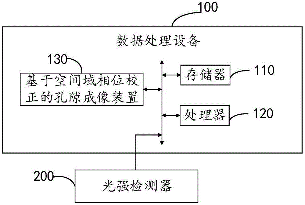
[0016] like figure 1 Shown is a schematic connection block diagram of the data processing device 100 and the light intensity detector 200 pr...

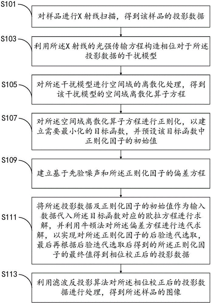
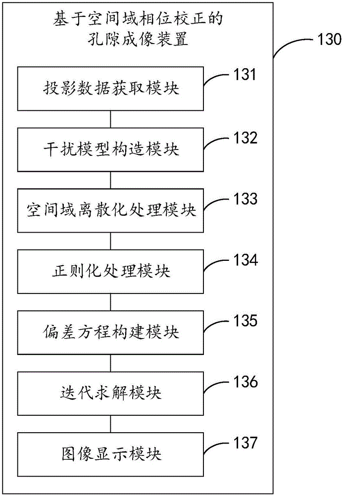

PUM


Abstract

The invention provides a pore imaging method and device based on spatial domain phase correction. According to the method, a spatial domain discretization operator equation is established for a constructed phase interference model to projection data and is solved by virtue of a Tikhonov Regularization method and an iteration method, and then an imaging result with relatively high resolution, result stability and fastconvergence speed is obtained, so that the purposes of increasing the pore imaging resolution of a sample and reducing the phase information interference and relative errors are achieved, and nano-scale pore throats and millimeter-micron-scale pore of the sample can be finely depicted.

Description

technical field [0001] The invention relates to the technical field of geophysical detection, in particular to a pore imaging method and device based on phase correction in the space domain. Background technique [0002] In recent years, micro-nano CT technology has been more widely used in fields including geology, geochemistry, and geophysics. Taking shale as an example, due to its special shale oil and gas storage method, the distribution of nano-scale pore throats inside Research is extremely important. It is difficult to study the micro-nano pores of shale non-destructively by traditional methods. Even X-ray scanning still has problems such as insufficient resolution, low signal-to-noise ratio, and difficulty in imaging weakly absorbing objects. , there will be serious phase interference problems. At present, the method of using phase information to process X-ray projection data mostly adopts the filtering method in the frequency domain. This method eliminates the inf...

Claims


Application Information

Patent Timeline
IPC IPC(8): G01N23/04
CPCG01N23/04G01N2223/401G01N2223/606G01N2223/616G01N2223/649
Inventor 王彦飞唐巍
Owner INST OF GEOLOGY & GEOPHYSICS CHINESE ACAD OF SCI
Learn More