
Novel aeroelastic model for wind tunnel test of power transmission tower structure

A technology of wind tunnel experiment and aeroelastic model, which is applied in the testing of machine/structural components, aerodynamic testing, measuring devices, etc., which can solve the problem of similarity, failure to satisfy the structure prototype of transmission tower, and the geometry of transmission tower structure prototype. Problems such as similarity and similarity in mass distribution achieve the effect of simple manufacturing process and convenient research on wind load characteristics

Inactive Publication Date: 2017-01-04
NORTH CHINA ELECTRIC POWER UNIV (BAODING)
View PDF5 Cites 11 Cited by
  • Summary
  • Abstract
  • Description
  • Claims
  • Application Information

AI Technical Summary

Problems solved by technology

[0003] At present, the existing aeroelastic models of transmission towers mainly have the following problems: 1. The geometric similarity and mass distribution of the prototype of the transmission tower cannot be satisfied; 2. The similarity of damping, frequency and stiffness distribution to the prototype of the transmission tower cannot be satisfied at the same time ; 3. The eddy current shedding effect and aerodynamic characteristics of the transmission tower structure under wind load excitation cannot be accurately simulated

Method used


Image

  • Novel aeroelastic model for wind tunnel test of power transmission tower structure
  • Novel aeroelastic model for wind tunnel test of power transmission tower structure
  • Novel aeroelastic model for wind tunnel test of power transmission tower structure

Examples


Embodiment Construction

[0017] The present invention will be further specifically described below in conjunction with the accompanying drawings and embodiments.

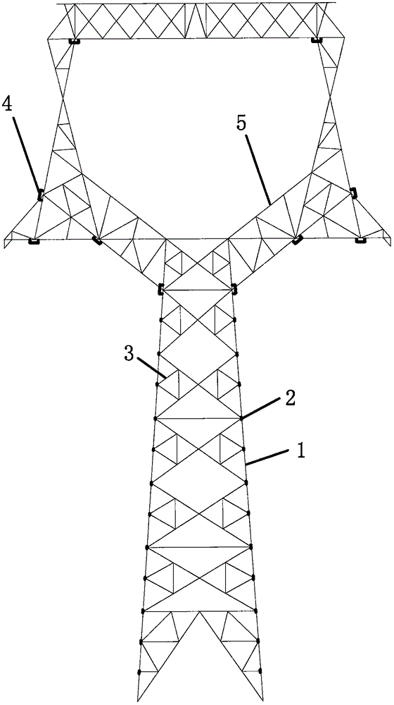
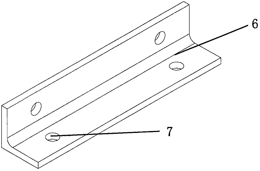
[0018] Such as figure 1 The aeroelastic model of a new type of transmission tower structure wind tunnel experiment of the present invention is shown, comprising: curved arm (5), angle steel section (3), n-type spring piece (4), copper wire (6) and tower frame Skeleton body (1); the tower frame body (1) is formed by connecting angle steel-shaped aluminum sections (3) through bolts (7) processed according to geometric similarity; crank arm (5) is made of angle steel The aluminum material segments (3) are formed by connecting (4) through n-type spring pieces, and metal wires (6) for counterweight are arranged inside the angle steel-type segments.

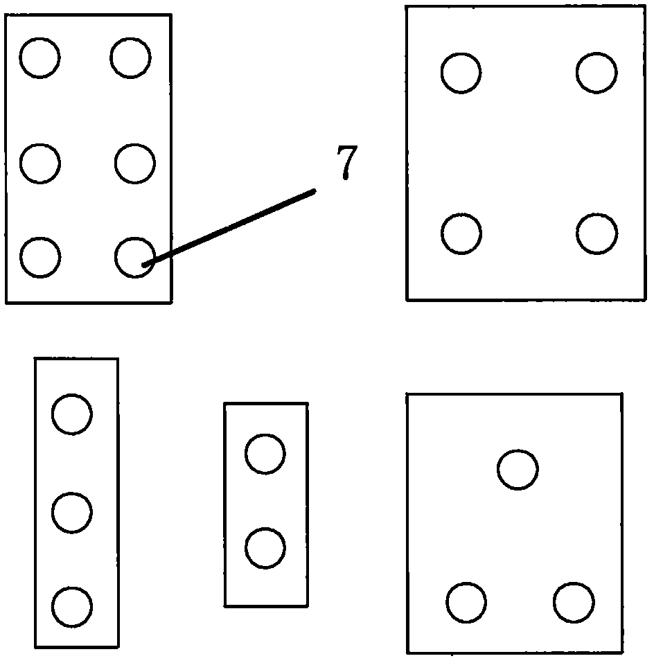
[0019] The aeroelastic model skeleton body (1) of the transmission tower is composed of angle-steel-shaped aluminum sections (3) connected by bolts (7) of different cross-sectional sizes and length...


PUM


Abstract

The invention discloses a novel aeroelastic model for a wind tunnel test of a power transmission tower structure, and belongs to the technical field of the design of power transmission lines. The novel aeroelastic model for the wind tunnel test of the power transmission tower structure comprises crank arms, angle steel type segments, n-type spring sheets, copper wires, and a tower skeleton body, the tower skeleton body is formed by connection of angle steel type aluminium segments which are formed by machining according to geometric similarity through bolts, the crank arms are formed by connection of the angle steel type aluminium segments through the n-type spring sheets, and the inner sides of the angle steel type segments are provided with counterweight metal wires. According to the aeroelastic model, the rigidity similarity of the aeroelastic model is guaranteed through adjustment of geometric parameters of the spring sheets, the similarity of parameters such as mass, damping, frequency, and geometry etc. is realized by employing the counterweight of the metal wires and the angle steel type aluminium segments reduced with equal proportion, the aerodynamic force characteristic of the power transmission tower by the wind load can be accurately simulated, the wind tunnel test of the model can obtain real and reliable data, and the research of the wind load characteristic of the power transmission tower is facilitated.

Description

technical field [0001] The invention belongs to the technical field of transmission line design and relates to a novel aeroelastic model for wind tunnel experiments of transmission tower structures in the technical field of wind load experiments. Background technique [0002] With the construction and development of high-voltage and ultra-high-voltage transmission lines, the height of high-voltage transmission towers and the span of lines are getting larger and larger. The transmission tower structure is more prone to aerodynamic instability under external excitation, resulting in large vibrations of the transmission tower, and even tower collapse accidents, which seriously threaten the safe and stable operation of the transmission line. The transmission tower is a flexible structure, which will produce a large response under the action of wind load. The mechanism of the wind effect of the tower structure is very complicated, and it cannot be completely solved in theory. The...

Claims


Application Information

Patent Timeline
IPC IPC(8): G01M9/08
CPCG01M9/08
Inventor 周超李力刘衍平
Owner NORTH CHINA ELECTRIC POWER UNIV (BAODING)
Learn More